Decompression device for engine

A decompression device and engine technology, applied in the direction of engine components, machines/engines, valve devices, etc., can solve the problem of reducing engine performance, increasing the weight of the exhaust side rocker arm 104, increasing the manufacturing cost of the exhaust side rocker arm 104, etc. problems, to save processing work, reduce manufacturing costs, and reduce weight

Inactive Publication Date: 2012-05-09
SUZUKI MOTOR CORP
View PDF5 Cites 4 Cited by
  • Summary
  • Abstract
  • Description
  • Claims
  • Application Information

AI Technical Summary

Problems solved by technology

[0010] However, when having Figure 10 and Figure 11 In the decompression device 117 of the structure shown, the protruding portion 116 is formed on the exhaust side rocker arm 104, thereby increasing the weight of the exhaust side rocker arm 104, thereby reducing the allowable revolution (rpm) of the engine and reduced engine performance
[0011] Also, since the protruding portion 116 is formed on the exhaust side rocker arm 104 , there is a need to process the protruding portion 116 , thus increasing the manufacturing cost of the exhaust side rocker arm 104

Method used


Image

  • Decompression device for engine
  • Decompression device for engine
  • Decompression device for engine

Examples


Embodiment Construction

[0029] Hereinafter, preferred embodiments of the present invention will be described with reference to the accompanying drawings. However, the present invention is not limited to these embodiments. It should also be noted that the terms "upper", "lower", "right" and "left" etc. showing directions and the like are used herein with reference to illustrations in the drawings or actual installation states of components.

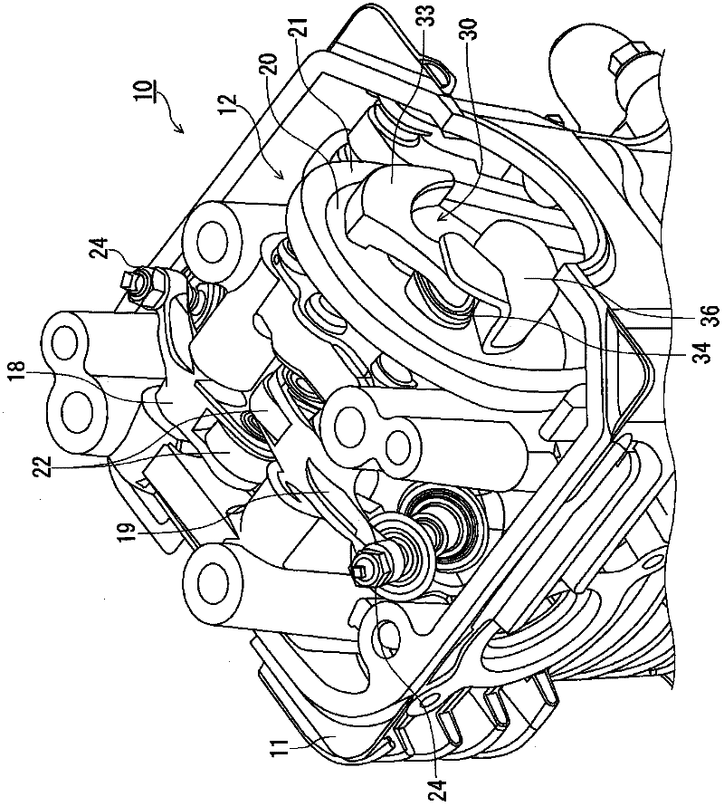
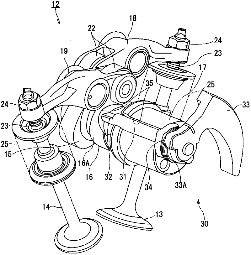
[0030] figure 1 and figure 2 shows an engine comprising a valve train with the cylinder head removed, the valve train being provided with a decompression device for an engine according to the invention, cf. figure 1 and figure 2 A four-stroke (four-stroke cycle) single-cylinder engine 10 includes a SOHC (Single Overhead Camshaft) type valve train (valve train) 12 arranged in a cylinder head 11 .

[0031] The valve train 12 includes an intake valve 13, an exhaust valve 14, a camshaft 17, an intake side rocker arm 18 and an exhaust side rocker arm 19, and a...


PUM


Abstract

The present invention provides a decompression device for an engine, wherein the engine comprises a valve transmission mechanism. In the valve transmission mechanism, a roller of a rocking arm rolls among a contour of a cam which is equipped on a cam shaft, and furthermore the rocking arm drives for opening / closing the valve. In the decompression device, a decompression shaft and a decompression roller are rotatably accommodated in a decompression tank which is formed in a cam shaft of a base circle part with a cam. The decompression shaft comprises a decompression cam at one end and a decompression arm at the other end. The track of the shaft is assumed at the base circle part of the cam. The shaft contacts with the track of the roller. The tank end of the decompression tank is formed at the base circle part of the cam. Furthermore in the track of the roller, the tangential line of each point on the tank end is crossed with the axis of the cam shaft.

Description

technical field [0001] The present invention relates to a decompression device for an engine included in a valve gear mechanism (or valve train mechanism) of a four-stroke engine. Background technique [0002] For example, Figure 8 A perspective view of a valve train including a conventional pressure relief device is shown. [0003] refer to Figure 8 , generally, in the valve train 100 of the engine, the intake side rocker arm 103 and the exhaust side rocker arm 104 are mainly are classified as Figure 8 Shown is a roller type including a roller 108 and a slider type shown in, for example, Patent Document 1 (Japanese Patent Laid-Open No. 2008-190423 ), in which the intake-side rocker arm 103 and the exhaust-side rocker arm 104 are driven into Valve 101 and exhaust valve 102. [0004] For the roller-type intake-side rocker arm 103 and exhaust-side rocker arm 104, the roller width of the roller 108 (such as Figure 9 shown) defines the width of the contact surface with th...

Claims


Application Information

Patent Timeline
Patent Type & Authority Applications(China)
IPC IPC(8): F01L13/08
CPCF01L13/085
Inventor 井户正敏神谷洋三
Owner SUZUKI MOTOR CORP
Why Eureka
Try Eureka