Pneumatic reversing valve

A technology of air-controlled reversing valve and reversing valve, which is applied in the direction of fluid pressure actuators, servo motor components, fluid pressure actuation system components, etc., which can solve the problems of large size, difficult transportation, heavy weight, etc. The effect of volume, saving installation pipeline and short working time

Inactive Publication Date: 2012-05-09
CHONGQING HANGYU IND
View PDF5 Cites 4 Cited by
  • Summary
  • Abstract
  • Description
  • Claims
  • Application Information

AI Technical Summary

Problems solved by technology

[0004] The traditional air-operated reversing valve is equipped with a safety valve, which makes it heavy, bulky and difficult to carry

Method used


Image

  • Pneumatic reversing valve
  • Pneumatic reversing valve
  • Pneumatic reversing valve

Examples


Embodiment Construction

[0021] The present invention will be described in further detail below in conjunction with specific embodiments and accompanying drawings.

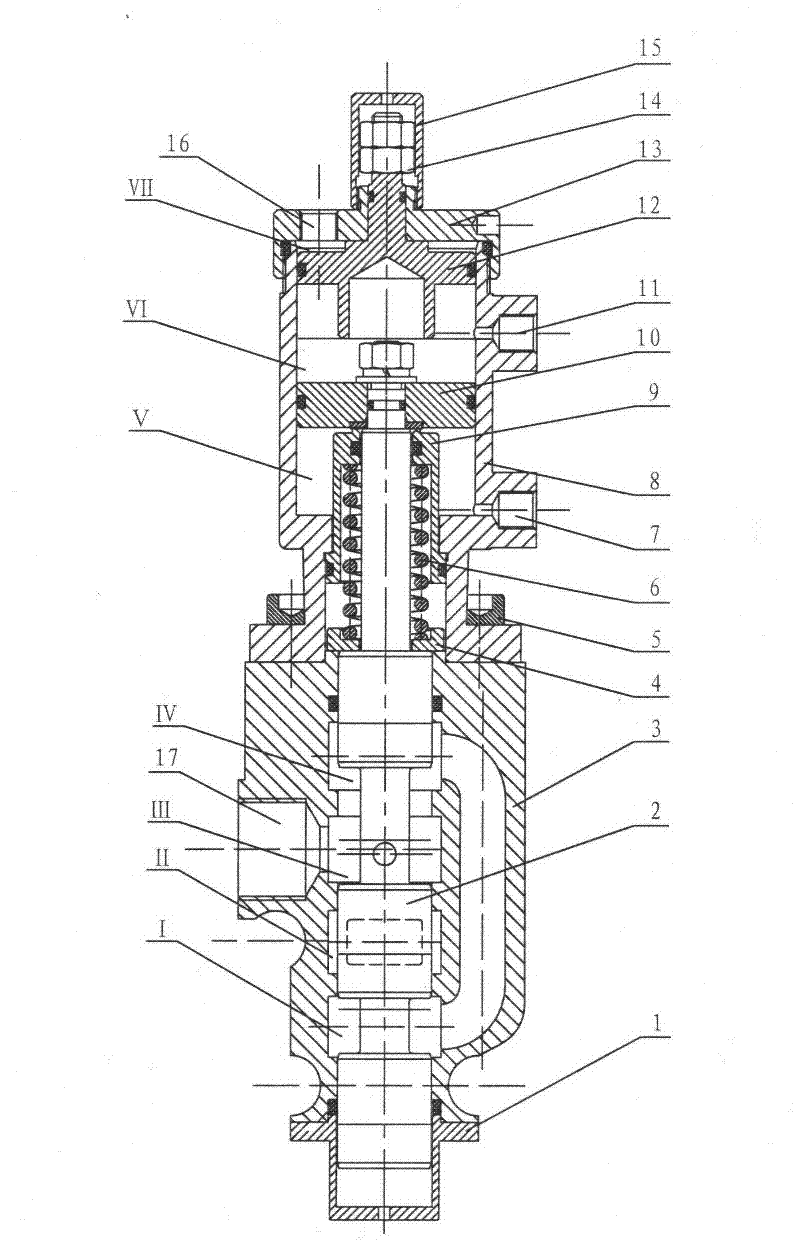
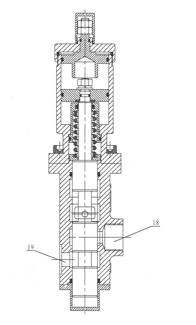
[0022] See Figure 1 to Figure 3 , the air-controlled reversing valve includes a valve body 3, a cylinder 8 and a mandrel 2, the valve body 3 is fixedly connected to the cylinder 8, and has a slide valve hole communicating with the valve body 3 and the cylinder 7 , the mandrel 2 is slidably arranged in the spool hole, and a return spring 6 is arranged on the mandrel 2;

[0023] Oil return chambers I, IV, oil outlet chamber II, and oil inlet chamber III are formed between the mandrel 2 and the valve body 3, and the valve body 3 is respectively provided with an oil return port 19, an oil outlet port 18, and an oil inlet chamber. The port 17 corresponds to the oil return chamber I, the oil outlet chamber II and the oil inlet chamber III one by one;

[0024] The mandrel 2 divides the interior of the cylinder 8 into two air chambers V, VI th...


PUM


Abstract

The invention discloses a pneumatic reversing valve, comprising a valve body, a cylinder and a core shaft, wherein the valve body is fixedly connected with the cylinder; the core shaft is arranged in a sliding valve hole for communicating the valve body with the cylinder in a sliding manner, and is provided with a return spring; an oil return cavity, an oil discharging cavity and an oil feeding cavity as well as an oil return port, an oil outlet and an oil inlet corresponding to the oil return cavity, the oil discharging cavity and the oil feeding cavity respectively are formed between the core shaft and the valve body; the core shaft divides the cylinder into two gas chambers by a piston arranged at the end part of the core shaft, and is respectively and correspondingly provided with a lifting port and a falling port; and the end part of the piston in the cylinder is provided with a slow-falling piston, and the gas chamber formed by the slow-falling piston and the end part of the cylinder is provided with a slow-falling port. The reversing valve and a pump are fixedly connected into a whole by a fixedly-connected bolt; the oil return port of the reversing valve is communicated with an oil feeding pipe of the pump; an oil outlet of the pump is communicated with the oil inlet of the reversing valve by a connecting pipe; the oil outlet of the reversing valve is connected with an oil inlet of an oil cylinder by a high-pressure oil pipe; and the pump is connected with a hydraulic oil tank by an oil pipe. According to the pneumatic reversing valve, the volume is small, the weight is light, and the service life is long.

Description

technical field [0001] The invention relates to a reversing valve, in particular to an air-controlled reversing valve for a dump truck and its application. Background technique [0002] The dump truck air-controlled reversing valve is the control valve for the dump truck to realize the lifting action. It cooperates with the hand-operated valve such as the control air valve to complete the actions of "lifting, mid-stop, lowering, and slow lowering" of the carriage. The reversing valve is a two-way air-controlled slide valve. When the air-controlled pressure is accidentally lost, it will automatically select the "intermediate stop" position to prevent the carriage from falling suddenly and ensure the safety of people and vehicles. [0003] At present, the air-controlled reversing valves in China are all fixed on the hydraulic oil tank, and the oil return port of the reversing valve is directly connected with the oil tank. The oil port is connected to the oil inlet of the oil ...

Claims


Application Information

Patent Timeline
Patent Type & Authority Applications(China)
IPC IPC(8): F15B13/02F15B21/00
Inventor 徐援朝
Owner CHONGQING HANGYU IND
Why Eureka
Try Eureka