Wheel blocking hydraulic station of rotary kiln

A technology of hydraulic station and rotary kiln, which is applied in the direction of rotary drum furnace, fluid pressure actuator, furnace, etc., and can solve the problems that the hydraulic system is difficult to reach, does not allow crawling and vibration, etc.

Inactive Publication Date: 2012-05-09
大连维乐液压制造有限公司
View PDF3 Cites 1 Cited by
  • Summary
  • Abstract
  • Description
  • Claims
  • Application Information

AI Technical Summary

Problems solved by technology

[0002] In the prior art, the rotary kiln requires the hydraulic cylinder of the retaining wheel to run smoothly at a speed of 50mm / h during operation, and no crawling and vibration are allowed. This is a difficult point in fluid transmission design, and it is very difficult for general hydraulic systems. difficult to meet this requirement

Method used


Image

  • Wheel blocking hydraulic station of rotary kiln
  • Wheel blocking hydraulic station of rotary kiln
  • Wheel blocking hydraulic station of rotary kiln

Examples


Embodiment Construction

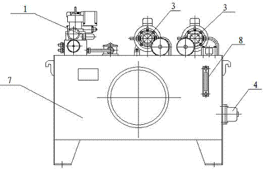
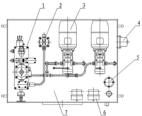
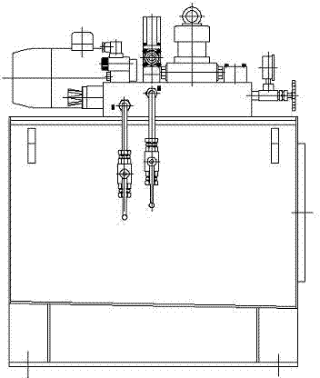
[0012] Such as figure 1 , figure 2 , image 3 with Figure 4 As shown, the rotary kiln retaining wheel hydraulic station includes control valve group 1, oil return filter device 2, pump device 3, heater 4, liquid level control device 5, oil temperature control device 6 and oil tank 7, control valve group 1, The oil return filter device 2, the pump device 3, the liquid level control device 5, and the oil temperature control device 6 are installed on the top of the oil tank 7, the heater 4 is installed on the side wall of the oil tank 7, and the control valve group 1 is connected to the oil return filter device through the pipeline. 2 connection, the control valve group 1 and the oil return filter device 2 are respectively connected to the pump device 3 through pipelines, the liquid level control device 5 is set on the pump device 3, and the hydraulic station is equipped with an oil inlet circuit speed regulation and a bypass oil circuit speed regulation The combined speed r...


PUM


Abstract

The invention disclose a wheel blocking hydraulic station of a rotary kiln, which comprises a control valve group, a return oil filtering device, a pump device, a heater, a liquid level control device, an oil temperature control device and an oil tank, wherein the control valve group, the return oil filtering device, the pump device, the liquid level control device and the oil temperature control device are mounted on the top of the oil tank; the heater is arranged on the side wall of the oil tank; the control valve group is connected with the return oil filtering device through a pipeline; the control valve group and the return oil filtering device are connected with the pump device through pipelines respectively; the liquid level control device is arranged on the pump device; and the hydraulic station is provided with a combined speed regulating loop of an inlet oil line speed regulating loop and a bypass oil line speed regulating loop. The wheel blocking hydraulic station of the rotary kiln disclosed by the invention not only provides a control loop which is available for super-low-speed steady running for the fluid design field, even more important, expands the design idea of super-low-speed steady running. The wheel blocking hydraulic station of the rotary kiln can be applied not only to speed control of a rotary kiln for producing powdered products but also to other occasions available for super-low-speed running.

Description

technical field [0001] The invention relates to a hydraulic station for retaining wheels of a rotary kiln. Background technique [0002] In the prior art, the rotary kiln requires the hydraulic cylinder of the retaining wheel to run smoothly at a speed of 50mm / h during operation, and no crawling and vibration are allowed. This is a difficult point in fluid transmission design, and it is very difficult for general hydraulic systems. It is difficult to meet this requirement. Contents of the invention [0003] The object of the present invention is to provide a rotary kiln retaining wheel hydraulic station. [0004] The technical solution adopted by the present invention to achieve the above purpose is: a rotary kiln retaining wheel hydraulic station, including a control valve group (1), an oil return filter device (2), a pump device (3), a heater (4), Liquid level control device (5), oil temperature control device (6) and oil tank (7), the control valve group (1), return o...

Claims


Application Information

Patent Timeline
Patent Type & Authority Applications(China)
IPC IPC(8): F27B7/22F15B11/04
Inventor 张久海丁维力
Owner 大连维乐液压制造有限公司
Why Eureka
Try Eureka