Asynchronous motor frame

A technology of electric motors and machine bases, applied in the field of electric motors, can solve problems such as failure to solve temperature rise control

Active Publication Date: 2016-01-13
ANHUI WANNAN ELECTRIC MACHINE
View PDF7 Cites 1 Cited by
  • Summary
  • Abstract
  • Description
  • Claims
  • Application Information

AI Technical Summary

Problems solved by technology

However, such a structure fails to solve the problem of temperature rise control in the development process of the motor, thereby broadening the design ideas of the motor and reducing the production cost

Method used


Image

  • Asynchronous motor frame
  • Asynchronous motor frame
  • Asynchronous motor frame

Examples


Embodiment Construction

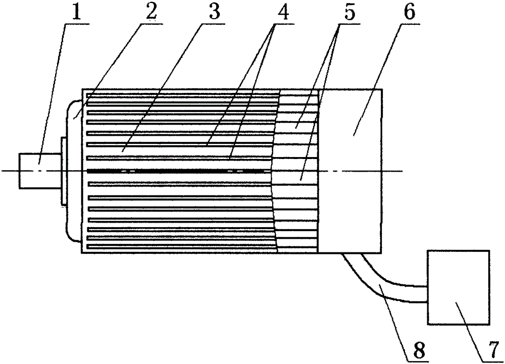
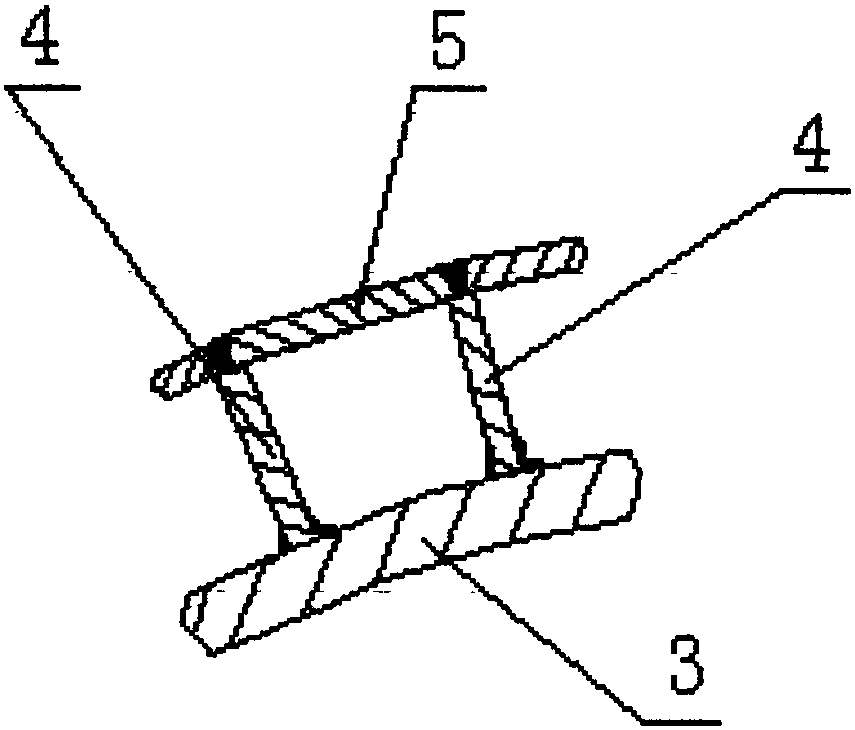
[0013] like figure 1 , figure 2 , image 3 As shown, an asynchronous motor cooling device includes a blower mechanism 7, a wind cover 6, a base body 3 and a front end cover 2 close to the motor output shaft 1, the wind cover 6 is located at one end of the base body 3, and the front cover 2 is located at the end of the machine base body. On the other end of the base body 3, the blower mechanism 7 communicates with the wind cover 6. There are a plurality of cooling ribs 4 on the base body 3, and each cooling rib 4 is parallel to the axis of the motor output shaft 1. Every two adjacent cooling ribs The top ends of the ribs 4 are provided with integrated strip plates 5 , and the machine base body 3 , multiple cooling ribs 4 and multiple strip plates 5 form a tubular channel with a special-shaped cross section. The frame body 3, the front end cover 2, the cooling rib 4, the strip plate 5 and the wind cover 6 are parts of the asynchronous motor frame respectively, and the strip p...


PUM


Abstract

The invention discloses an asynchronous motor seat. The asynchronous motor seat comprises a fan cover, a motor seat body, and a front end cover close to a motor output shaft, wherein the fan cover is located at one end of the motor seat body, the front end cover is located at other end of the motor seat body, a plurality of heat-dissipation ribs are arranged on the motor seat body, each heat-dissipation rib is parallel with the axis of the motor output shaft, an integrally formed strip-type plate is arranged at the top ends of every two adjacent heat-dissipation ribs, and the motor seat body, the plurality of heat-dissipation ribs and a plurality of the strip-type plates form a tubular passageway with a special-shaped cross section. By means of the structure, the asynchronous motor seat can reinforce the heat-dissipation capacity after use, effectively improves the heat-dissipation situation, further effectively lowers the temperature rise of a motor, provides an effective technical scheme for temperature rise control in the development process of motors, widens the design thought of the motor, and lowers manufacturing cost.

Description

technical field [0001] The present invention relates to electric motors, in particular to an asynchronous motor frame. Background technique [0002] Temperature rise is an important index in the design and operation of the motor. When the motor is running, the greater the output power, the greater the current and loss, and the higher the temperature, but the maximum temperature must not exceed the maximum allowable temperature of the insulation. Therefore, the allowable temperature of the motor The rated power is limited by the maximum allowable temperature of the insulation. At present, motor design pursues high rated power and small volume, but temperature rise is a difficult problem to be solved. The methods to reduce the temperature rise include increasing the thickness of the stator core, changing the wire diameter of the winding coil, changing the rotor and changing the heat dissipation style, increasing the thickness of the stator core, and changing the wire diameter...

Claims


Application Information

Patent Timeline
Patent Type & Authority Patents(China)
IPC IPC(8): H02K5/18H02K5/20H02K5/04
Inventor 孙跃许洪清张忠根饶启明张柯彬欧阳山
Owner ANHUI WANNAN ELECTRIC MACHINE
Why Eureka
Try Eureka