Loading running-in device for ball screw pair and running-in testing method thereof

A ball screw pair and running-in technology, which is applied in the field of ball screw pair loading and running-in devices, can solve problems that cannot accurately reflect the performance of the ball screw pair, cannot simulate the force environment of the ball screw pair, and hydraulic cylinders Complicated structure and other issues, achieve the effects of small footprint, improved factory performance, and reduced labor intensity

Active Publication Date: 2012-05-09
中润海精密科技有限公司
View PDF9 Cites 18 Cited by
  • Summary
  • Abstract
  • Description
  • Claims
  • Application Information

AI Technical Summary

Problems solved by technology

The application converts the external load into the internal force of the system, so that the nut and the screw bear an axial load, and a section of the screw between the two nuts bears an internal tension. When the screw is rotated, the nut moves back and forth. , there is alternating contact stress on the nut and the screw raceway, which realizes that the life of the testing machine is longer than that of the ball screw pair, and ensures that the test can be completed continuously at one time. However, the shortcomings of this application lie in: the structure of the hydraulic cylinder is complex, And the frequent reciprocating movement of the oil cylinder is easy to wear and tear, resulting in oil le...

Method used


Image

  • Loading running-in device for ball screw pair and running-in testing method thereof
  • Loading running-in device for ball screw pair and running-in testing method thereof
  • Loading running-in device for ball screw pair and running-in testing method thereof

Examples


Embodiment

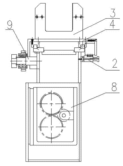
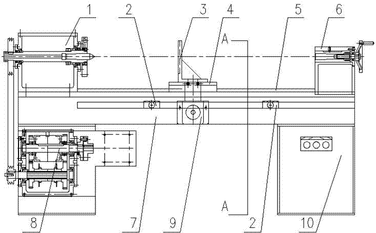
[0045] In the loading and running-in device of the ball screw pair in this embodiment, the headstock 1 is fixed on one end of the bed 7 by bolts, the tailstock 6 is slid on the slide rail of the bed 7, and the headstock 1 and the tailstock 6 are located on the bed respectively. The two ends of the body 7, the tailstock 6 can move on the slide rail of the bed 7, the tops of the headstock 1 and the tailstock 6 are located on the same horizontal line, and the ball screw pair is clamped on the headstock and the headstock through the central holes at both ends. The top ends of the tailstock are strengthened and fixed by the chuck on the headstock 1, the carriage 4 is sleeved on the guide rail 5, and can slide in the axial direction of the guide rail 5, and the positioning plate 3 is fixed on the carriage 4 by screws , the positioning plate 3 is located above the carriage 4, the positioning plate 3 is provided with a U-shaped groove, the two sides of the U-shaped groove are provided ...


PUM


Abstract

The invention discloses a loading running-in device for a ball screw pair and a running-in testing method thereof, which belong to the technical field of running-in test of ball screw pairs. In the running-in device, a main spindle box and a tail seat are used for fixing a ball screw pair; a positioning plate is fixedly connected with a ball nut of the ball screw pair; automatic reversing running-in of the ball screw pair is realized by using a limit switch and a limit switch triggering rod; a magnetic powder brake is used for applying an axial load to the ball screw pair; a reversing mechanism is used for controlling positive and negative rotation of a tip; and a control cabinet is used for controlling other devices to work. The running-in test method comprises the following steps of: loading the ball screw pair; fixing the ball nut; performing a running-in procedure; parking; and testing performance parameters and unloading the ball screw pair. In the invention, the axial load is applied to the ball screw pair by using the magnetic powder brake, so that the delivery performance of the ball screw pair is enhanced; and the magnitude of the loaded load is easy to control, so that temperature rise of the ball screw pair after running-in can be tested accurately and conveniently.

Description

technical field [0001] The invention relates to a test device and a test method for a ball screw pair, more specifically, to a loading and running-in device and a running-in test method for a ball screw pair that applies an axial load through a magnetic powder brake. Background technique [0002] Running-in is one of the processes in the production of ball screw assemblies, and each set of ball screw assemblies needs to be run-in before leaving the factory to improve its performance. In the past, the running-in of the ball screw pair was carried out under the condition of zero load. In this case, it is impossible to know the temperature rise of the ball screw pair after running-in, whether the ball circulation reverse device is firm or falls off, and whether the sealing ring is Whether it is firm, deformed and dislocated, and whether the dynamic no-load preload torque of the ball screw pair still meets the requirements of the drawings, etc. [0003] The Chinese patent appli...

Claims


Application Information

Patent Timeline
IPC IPC(8): G01M13/02
Inventor 于宙
Owner 中润海精密科技有限公司
Why Eureka
Try Eureka