Manufacturing method of program switch and terminal assembly for improving manufacturing efficiency

A manufacturing method and combined technology, which are applied to electrical switches, electrical components, circuits, etc., can solve the problems of increased manufacturing cost, reduced size, and high manufacturing cost of the program switch 1, and achieve the effect of improving overall manufacturing efficiency and reducing time.

Active Publication Date: 2012-05-09
EXCEL CELL ELECTRONICS
View PDF4 Cites 0 Cited by
  • Summary
  • Abstract
  • Description
  • Claims
  • Application Information

AI Technical Summary

Problems solved by technology

[0006] 1. Due to the structural design of the program switch 1, when assembled and installed, the fixed terminal 131 and the movable terminal 132 must be manually inserted into the first positioning hole 111 and the first positioning hole 111 of the base 11 respectively. The second positioning hole 112 can enable the fixed terminal 131 and the movable terminal 132 to be stably positioned. Then, by making the cover shell 12 and the base 11 fit together, the toggle member 14 is clamped on the The combination of the program switch 1 is completed only between the base 11 and the cover shell 12. Therefore, in the step of inserting the fixed terminal 131 and the movable terminal 132 of the existing program switch 1, more manpower is required. And time, resulting in poor process efficiency, and has the disadvantages of high man-hours and high manufacturing costs
[0007] 2. In order to prevent the fixed terminals 131 and the movable terminals 132 from being scattered during the assembly process, the first positioning hole 111 and the second positioning hole 112 must be formed on the base 11 for the terminals 131 and 132 to be plugged in. In response to the demand for miniaturization of electronic products, the size of the base 11 also needs to be reduced. Under the specification of size miniaturization, it is necessary to precisely form the fixed terminal 131 on the base 11 so that the movable terminals 131 and The first positioning hole 111 and the second positioning hole 112 for the stable positioning of the terminal 132 will make the design of the molding die of the base 11 relatively complicated, which will also increase the difficulty of manufacturing and lead to an increase in the overall manufacturing cost of the program switch 1

Method used


Image

  • Manufacturing method of program switch and terminal assembly for improving manufacturing efficiency
  • Manufacturing method of program switch and terminal assembly for improving manufacturing efficiency
  • Manufacturing method of program switch and terminal assembly for improving manufacturing efficiency

Examples


Embodiment Construction

[0038] The present invention will be described in detail below in conjunction with the accompanying drawings and embodiments.

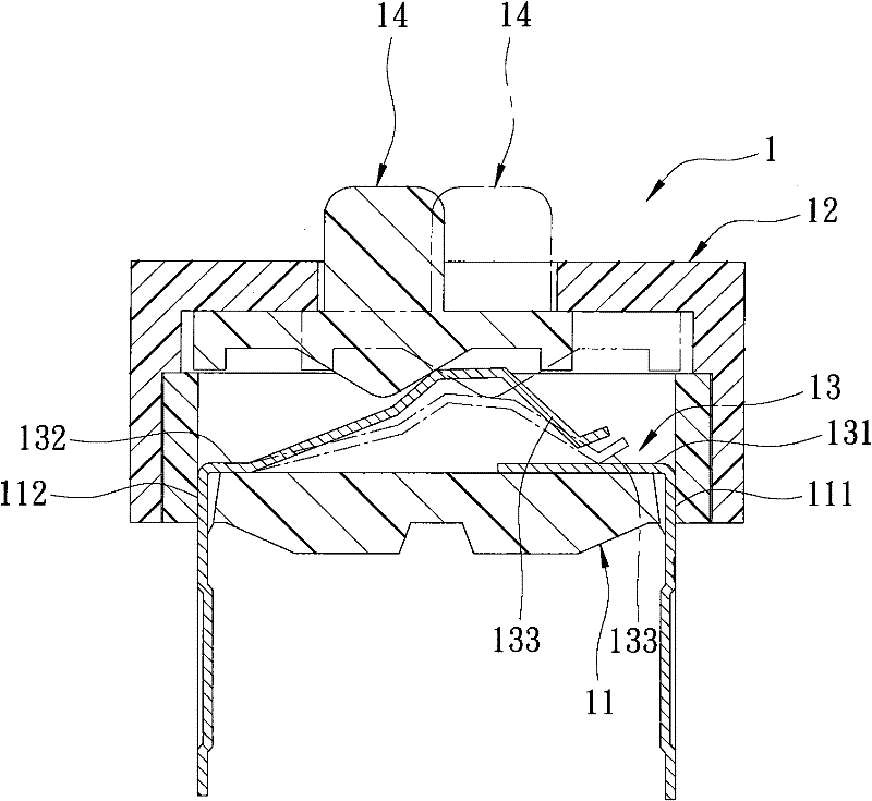
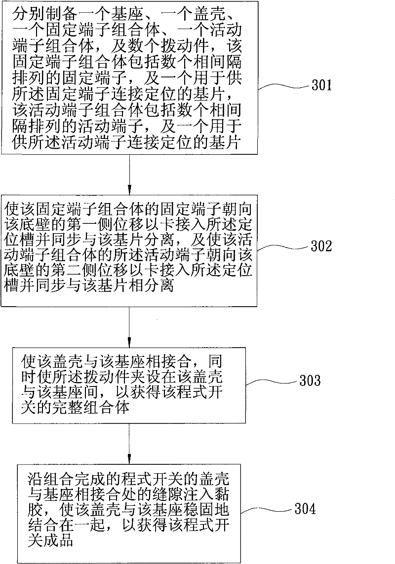
[0039] refer to image 3 and Figure 4 , the preferred embodiment of the manufacturing method of program switch 2 of the present invention comprises the following steps:

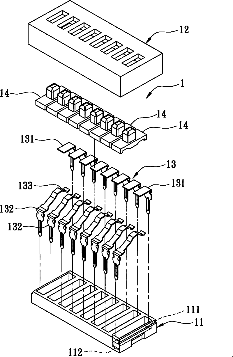
[0040] Step 301 is to prepare a base 4 , a cover shell 5 , a fixed terminal assembly 6 , a movable terminal assembly 7 , and several toggle pieces 8 .

[0041] Wherein, the base 4 is made of insulating material, and includes a bottom wall 41 with a first side 411 and a second side 412 opposite to each other, and several spaced apart extending upwards from the bottom wall 41 and Cooperate with and define the partition walls 42 forming a plurality of positioning grooves 420 . The bottom wall 41 also has several first slots 413 recessed from the first side 411 at intervals to communicate with the positioning groove 420, and several recesses at intervals from the second side 412 to c...


PUM


Abstract

The invention discloses a manufacturing method of program switch and a terminal assembly for improving manufacturing efficiency. The manufacturing method comprises a step of respectively manufacturing a substrate, a cover shell, a fixed terminal assembly, a movable terminal assembly and a plurality of toggle pieces. The fixed terminal assembly comprises a plurality of fixed terminals and a chip for positioning fixed terminals; and the movable terminal assembly comprises a plurality of movable terminals and a chip for positioning movable terminals. When the fixed terminal assembly and the movable terminal assembly are respectively mounted on the two opposite sides of the substrate, the fixed terminals and the movable terminals can be both conveniently combined with the substrate by a structure which is so designed as to respectively connect the fixed terminals and the movable terminals with the substrate integrally; in this way, time for mounting can be greatly shortened, the manufacturing efficiency of the invention is better, and manufacturing cost can be saved.

Description

technical field [0001] The invention relates to a method for manufacturing a program switch, in particular to a method for manufacturing a program switch that can be quickly combined and installed and a terminal assembly for improving manufacturing efficiency. Background technique [0002] refer to figure 1 and figure 2 , an existing program switch 1 has a base 11 correspondingly joined and made of an insulating material, a cover shell 12, a terminal unit 13 arranged on the base 11, and several terminals respectively arranged on the base 11 and the The toggle piece 14 between the cover shells 12 . [0003] The base 11 has several first positioning holes 111 spaced through along one side thereof, and several second positioning holes corresponding to the first positioning holes 111 and spaced apart along an opposite side thereof. 112. [0004] The terminal unit 13 has several fixed terminals 131 spaced apart and respectively inserted in the first positioning hole 111, and...

Claims


Application Information

Patent Timeline
Patent Type & Authority Applications(China)
IPC IPC(8): H01H11/06
Inventor 李尉慈
Owner EXCEL CELL ELECTRONICS
Why Eureka
Try Eureka