A wire bonding fixture

A wire bonding and fixture technology, which is used in the manufacture of electrical components, electrical solid-state devices, semiconductor/solid-state devices, etc., can solve the problems of difficult to guarantee welding quality, poor chip consistency, low equipment utilization, etc. Improve consistency and ease of operation

Inactive Publication Date: 2014-10-15
BEIJING MXTRONICS CORP +1
View PDF10 Cites 0 Cited by
  • Summary
  • Abstract
  • Description
  • Claims
  • Application Information

AI Technical Summary

Problems solved by technology

The above-mentioned wire bonding fixture is not only complicated to operate, but also has a lot of pause time and low utilization rate of equipment
More importantly, since the fixture needs to be reinstalled once before each working surface is bonded, the consistency of the chip is poor, and the welding quality is difficult to guarantee

Method used


Image

  • A wire bonding fixture
  • A wire bonding fixture
  • A wire bonding fixture

Examples


Embodiment Construction

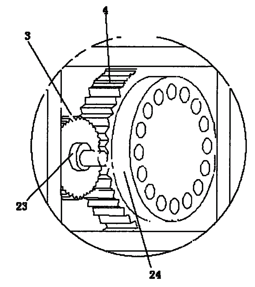
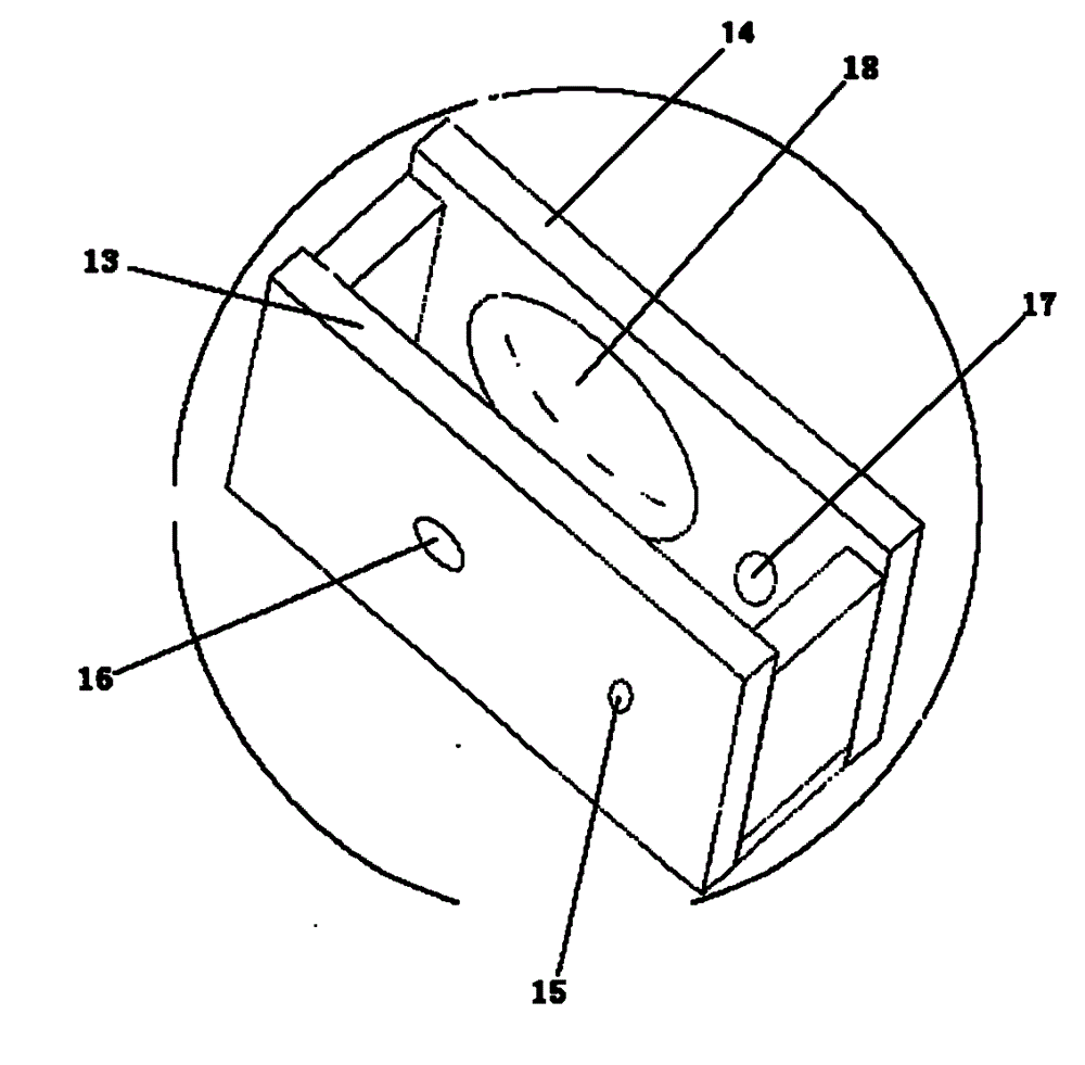
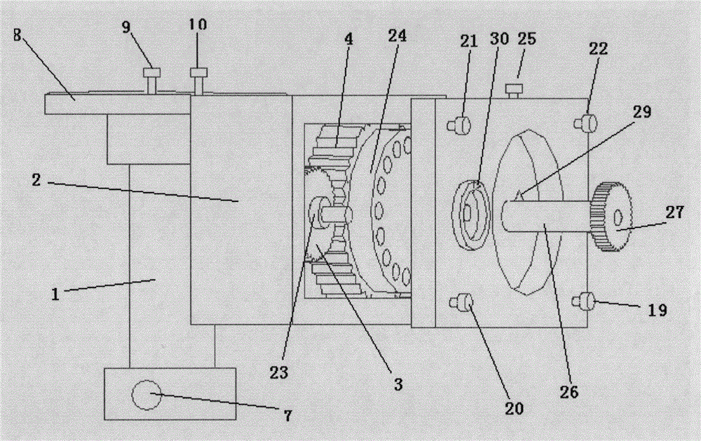
[0024] The invention designs a reasonable clamp structure. By adding a gear box in the clamp, the meshing of large and small gears is used to realize continuous switching of multiple sides in the three-dimensional space of the device. In addition, the present invention connects the fixed shaft with the gear box through the right-angle steering plate, so that the working direction of the clamp is horizontal, which is more convenient for operation. In the selection of the fixing method, the present invention mainly adopts the method of combining the socket fixing and the screw fixing, thereby improving the precision of the bonding. Such as figure 1 As shown, the core components of the present invention include a fixed shaft 1, a gear box 2, a small gear 3, a large gear 4, a small shaft 5, and a large shaft 6; Figure 5 As shown, there is a through hole in the fixed shaft 1 for connecting with the equipment workbench. The two ends of the fixed shaft 1 have integrally formed circula...


PUM


Abstract

The invention discloses a wire bonding clamp which comprises a fixed shaft, a gear box, a pinion, a bull wheel, a small shaft and a big shaft, wherein one end of the fixed shaft is connected with an equipment working platform, the other end of the fixed shaft is connected with the gear box, the bull wheel is meshed with the pinion, the small shaft and the big shaft are respectively center shafts of the pinion and the bull wheel, the bull wheel and the pinion are embedded inside the gear box, the end face of the bull wheel is provided with a bull wheel lug boss, and the end face of the bull wheel lug boss is provided with uniformly-distributed through holes for fixing a device to be clamped. The bull wheel is driven to rotate through rotation of the pinion, and the bull wheel drives the device fixed on the bull wheel to rotate simultaneously so that the device is switched into the next working face. The invention realizes continuous switching of a plurality of side surfaces in a three-dimensional space of the device, and avoids multiple times of installation of the device, thus suspend time of the wire bonding clamp is greatly saved and production efficiency is increased. The clamp is convenient and simple in operation; and processing precision is increased, and better welding quality is ensured.

Description

Technical field [0001] The invention relates to a wire bonding fixture, which can be used for continuous operations on multiple sides. Background technique [0002] In the wire bonding process of the 3D assembly device, it usually involves the bonding of multiple sides of the 3D assembly device. The chip that needs to be bonded is pasted on the multiple sides of the 3D assembly device, and each chip is attached. The side is called the working surface. The 3D assembly device is clamped by the wire bonding fixture installed on the bonding machine, so that the bonding team can bond the chip. The existing wire bonding fixture can only complete the wire bonding of one working surface at a time. When the next working surface is needed for bonding, the device needs to be manually taken out and rotated to another working surface that needs to be bonded. The device is reinstalled on the fixture of the bonding machine. The above-mentioned wire bonding fixture is not only complicated to ...

Claims


Application Information

Patent Timeline
Patent Type & Authority Patents(China)
IPC IPC(8): H01L21/687
CPCH01L2924/01082H01L2924/00014H01L2224/78H01L24/78H01L2224/48H01L2924/00012
Inventor 陈建安冯小成练滨浩姚全斌
Owner BEIJING MXTRONICS CORP
Why Eureka
Try Eureka