Internal combustion engine system

a combustion engine and internal combustion technology, applied in the direction of machines/engines, non-mechanical valves, valve drives, etc., can solve the problems of above-described problems relevant to the combustion state, the change to the start profile does not necessarily succeed, and the unstable combustion state of the cylinder for which the change to the start profile is not completed, etc., to shorten the suspension time of the combustion.

Active Publication Date: 2019-11-05
TOYOTA JIDOSHA KK
View PDF20 Cites 0 Cited by
  • Summary
  • Abstract
  • Description
  • Claims
  • Application Information

AI Technical Summary

Benefits of technology

[0007]The disclosure has been made in view of the above-described problems. That is, an object of the disclosure is to prevent problems of the combustion state at the time of the start of the engine, in a multiple cylinder engine system in which the switching among a plurality of kinds of cams having different cam profiles is performed by a cam carrier provided for each corresponding cylinder or for each corresponding cylinder group.
[0010]According to the aspect, even in the case of the failure of the switching to the start cam at the time of the stop of the internal combustion engine, it is possible to perform the switching to the start cam at the time of the next start of the internal combustion engine, and to suspend the start of the combustion of the air-fuel mixture in each cylinder, until the switching is completed for all cylinders. That is, it is possible to start the combustion of the air-fuel mixture in each cylinder, after the switching to the start cam is completed for all cylinders at the time of the next start of the internal combustion engine. Accordingly, it is possible to prevent problems of the combustion state at the time of the next start of the internal combustion engine.
[0012]According to the aspect, at the time of the next start of the internal combustion engine, it is possible to perform the switching to the start cam, only for the corresponding cylinder or corresponding cylinder group that has failed to switch to the start cam at the time of the stop of the internal combustion engine. Accordingly, it is possible to suppress the amount of electric power to be consumed for the drive of the switching mechanism, compared to the case where the switching to the start cam is performed for all cylinders.
[0014]According to the aspect, it is possible to advance the order of the switching to the start cam at the time of the next start of the internal combustion engine, for the corresponding cylinder or corresponding cylinder group that has failed to switch to the start cam at the time of the stop of the internal combustion engine. Accordingly, it is possible to shorten a suspension time of the combustion of the air-fuel mixture in each cylinder at the time of the next start of the internal combustion engine, and to complete a start operation early.

Problems solved by technology

However, in the case where the cam carrier is provided for each corresponding cylinder or for each corresponding cylinder group, there is a possibility that the combustion state of a cylinder for which the change to the start profile is not completed becomes unstable, when the change to the start profile is performed in parallel with the start of the engine.
However, the change to the start profile does not necessarily succeed at the time of the previous stop.
If the engine is started in a state where some cam carriers have failed in the change to the start profile at the time of the previous stop, the above-described problems relevant to the combustion state occur.
However, when the stop of the engine is extended, there is a problem in that fuel consumption increases by an amount equivalent to the extension.
Further, there are various modes for the stop of the engine, and in some cases, the extension of the stop of the engine is originally impossible.
That is, in the case of an unexpected engine stop that is not based on a driver's intention or a control by an in-vehicle computer, there is a problem in that the change to the start profile is impossible at the time of the previous stop.

Method used


Image

  • Internal combustion engine system
  • Internal combustion engine system
  • Internal combustion engine system

Examples


first embodiment

[0025]To begin, the disclosure will be described with reference to FIGS. 1 to 5.

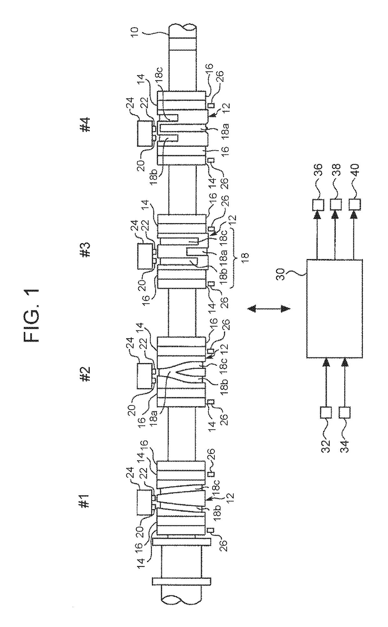
[0026]FIG. 1 is a schematic diagram showing an exemplary configuration of a system according to the first embodiment of the disclosure. The system shown in FIG. 1 is a system of an internal combustion engine that is mounted on a vehicle. The internal combustion engine is a four-stroke reciprocating engine, and is an inline-four engine. The firing order of the engine is the order of a number one cylinder #1, a number three cylinder #3, a number four cylinder #4 and a number two cylinder #2. The number of the cylinders of the engine may be two, may be three, or may be five or more. Further, the firing order of the engine is not particularly limited.

[0027]A valve train shown in FIG. 1 includes a camshaft 10. The camshaft 10 is connected to a crankshaft (not illustrated) of the engine, and rotates in synchronization with the crankshaft. On the camshaft 10, four cam carriers 12 formed as hollow shafts are dis...

second embodiment

[0057]FIG. 6 is a diagram showing an exemplary processing routine relevant to the start-time control that is executed by the ECU in the disclosure. The routine is executed whenever the start request for the engine is output, similarly to the routine shown in FIG. 5. The processes shown in the routine is basically the same as the processes in the routine shown in FIG. 5. Specifically, the processes in steps S16, S18, S24, S26 and S28 of FIG. 6 are the same as the processes in steps S2, S4, S10, S12 and S14 of FIG. 5. In the following, the processes in steps S20 and S22 of FIG. 6, which are partially different from the processes in FIG. 5, will be described.

[0058]In step S20 of FIG. 6, the above-described switching command is output to a solenoid actuator corresponding to the small-cam cylinder. As described above, it is found what cylinder is the small-cam cylinder, at the end time of the stop-time control. In the process in step S20, the small-cam cylinder is specified based on that...

third embodiment

[0062]FIG. 7 is a diagram for describing an exemplary during-stop control in the disclosure. In the example of FIG. 7, the stop request for the engine is output at time t1, and the engine speed becomes zero at time t2. The switching of the driving cams of the number one cylinder #1, the number three cylinder #3 and the number four cylinder #4 is performed in a period from time t1 to time t2. However, the switching of the driving cam of the number two cylinder #2 is not completed. So far, the content of the stop-time control is the same as the content of the stop-time control described in FIG. 4.

[0063]At time t2, it is found that the number two cylinder #2 corresponds to the small-cam cylinder. Hence, in the example of FIG. 7, at time t7 after time t2, the powering drive of the motor generator is started, and the crankshaft is rotated. By the rotation of the crankshaft, the stop position of the cam carrier is moved. In the example of FIG. 7, the drive of the motor generator is contin...


PUM


Abstract

In a system that selects a large-cam as a driving cam at a time of a start of an engine, when an engine stop request is output, it is determined whether there is a small-cam cylinder for which a small-cam is selected as the driving cam. In a case where it is determined that there is a small-cam cylinder, a switching command for switching the driving cam from the small-cam to the large-cam is output. When an engine start request is output, the above determination is performed again. In a case where it is determined that there is a small-cam cylinder, the switching command is output to all solenoid actuators again. In addition, the drive of the fuel injector is suspended until the switching operation of the driving cam is completed for all cylinders.

Description

INCORPORATION BY REFERENCE[0001]The disclosure of Japanese Patent Application No. 2017-027090 filed on Feb. 16, 2017 including the specification, drawings and abstract is incorporated herein by reference in its entirety.BACKGROUND1. Technical Field[0002]The disclosure relates to an internal combustion engine system.2. Description of Related Art[0003]Japanese Patent No. 5404427 discloses a valve operating device including a cam carrier that is provided on a camshaft of an engine and a servomechanism that slides the cam carrier in an axial direction of the camshaft. The cam carrier includes three kinds of cams that have different cam profiles and that are capable of driving an intake valve. On an outer peripheral surface of the cam carrier, a groove having a predetermined shape is formed. The groove having the predetermined shape includes an inclined portion that is inclined with respect to the axis of the camshaft. The servomechanism operates so as to push out an engagement element c...

Claims


Application Information

Patent Timeline
Patent Type & Authority Patents(United States)
IPC IPC(8): F01L1/34F01L13/00F01L1/08
CPCF01L1/08F01L13/0036F01L13/00F01L2800/03F01L2013/0052F01L2800/01F01L2800/11F01L1/06F01L1/146F01L9/20F01L1/047
Inventor SUGIHIRA, SHIGEHIROADACHI, NORIYASUSASAKI, KEISUKEKAWAI, TAKAYOSHIOTSUKA, KAORUSADAKANE, SHINJISUGIHARA, HIROYUKI
Owner TOYOTA JIDOSHA KK
Why Eureka
Try Eureka