
Non-blind-area multi-target cooperative tracking method and system

A multi-target, non-blind-spot technology, which is applied in closed-circuit television systems, TV system components, image data processing, etc., can solve problems such as single traffic road images, inability to see target details, monitoring blind spots, etc., to achieve the goal of safeguarding safety Effect

Inactive Publication Date: 2012-05-09
合肥博微安全电子科技有限公司
View PDF5 Cites 36 Cited by
  • Summary
  • Abstract
  • Description
  • Claims
  • Application Information

AI Technical Summary

Problems solved by technology

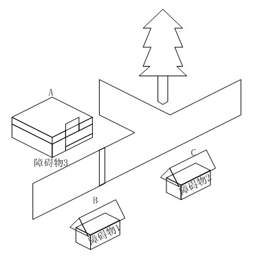
[0004] At present, there are many multi-target tracking methods for video surveillance. Among them, some methods often have some monitoring blind spots in actual scenes, and do not take into account the monitoring of blind spots; some methods use frame reduction and sub-sampling methods. So that it is impossible to see the details of the target; there are also methods that use multiple cameras to obtain traffic road images, and then splicing them into panoramic images to collaboratively track moving targets in large scenes. The demand for target monitoring, because the traffic road image is generally relatively single, and there are few blind spots, it can be spliced ​​into a large scene for multi-camera collaborative tracking of moving targets, but it cannot be applied to the occasions where the distribution of objects in the community or the scene is relatively complex, so there will be Many monitoring blind spots

Method used


Image

  • Non-blind-area multi-target cooperative tracking method and system
  • Non-blind-area multi-target cooperative tracking method and system
  • Non-blind-area multi-target cooperative tracking method and system

Examples


Embodiment Construction

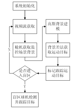
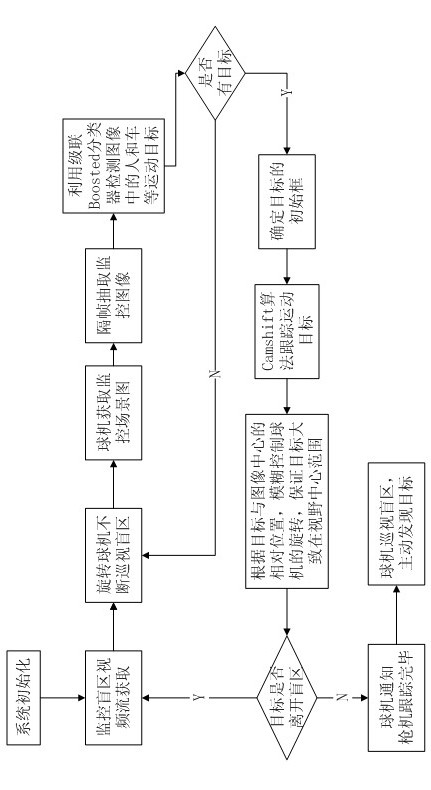
[0018] A method for multi-target cooperative tracking without blind spots, the method comprises the steps in the following order: (1) Manually delineate monitoring areas and blind spots in the background of gun camera monitoring, and place ball cameras in the corresponding blind spots; (2) Power-on initialization , obtain the image sequence of the bolt monitoring scene, carry out Gaussian background modeling to the monitoring image sequence, and obtain the background image; detect the moving target in the monitoring image, and obtain the moving target; the moving target is tracked and marked by the bolt; ( 3) The speed dome continuously detects whether there is a moving target in the blind area. After detecting the target, it tracks the moving target and sends the target position information back to the trigger. The trigger controls the movement of the dome according to the movement of the target to ensure that the target is roughly within The field of view center range of the ...


PUM


Abstract

The invention relates to a non-blind-area multi-target cooperative tracking method, which comprises the following steps of: manually designating a monitoring area or a blind area in a gun camera monitoring background, and arranging a dome in a corresponding blind area; obtaining an image sequence of a gun camera monitoring scene, and carrying out gauss background modeling to the monitoring image sequence to obtain a background image; detecting a moving target in a monitoring image to obtain the moving target; carrying out gun camera tracking and marking the detected moving target; and continuously detecting whether the moving target exists in the blind area by the gun camera, after determining the moving target, tracking the moving target, transmitting the target position information back to a gun camera, and controlling the movement of the dome according to the movement of the moving target so as to ensure that the moving target is generally within view central range of the dome. The invention also discloses a non-blind-area multi-target cooperative tracking system. According to the invention, as the dome and the gun camera cooperate for the interaction of movement target information, non-blind-area display is carried out in a unitive monitoring picture, the monitoring at all corners can be realized, and further, the safety of the monitoring area is guarded.

Description

technical field [0001] The invention relates to the field of intelligent video monitoring, in particular to a multi-target cooperative tracking method and system without blind spots. Background technique [0002] With the development of economy and information technology, people's demand for safety precautions is getting higher and higher. As an effective means in the field of safety prevention, video surveillance has a wider and wider range of applications, and the application requirements are constantly improving. Traditional video surveillance systems can only provide functions of video collection, storage, and post-event verification. If real-time monitoring is to be performed, abnormalities are found and alarms are required, monitoring personnel must continue to watch the display in the monitoring room to find abnormalities, which will not only increase It increases the cost of monitoring, and watching the display screen for a long time will cause visual fatigue, which ...

Claims


Application Information

Patent Timeline
IPC IPC(8): H04N5/232H04N7/18G06K9/66G06T7/20
Inventor 曾杰周金旺李彤张崴郑远见戴冲张珂
Owner 合肥博微安全电子科技有限公司
Learn More