
Device and method for controlling fluid flows in lab-on-a-chip systems and method for producing said device

A laboratory and control panel technology, applied to laboratory containers, laboratory utensils, chemical instruments and methods, etc., can solve problems such as high cost and trouble, and achieve reliable working mode, low failure rate and high reproducibility The effects of realism and reliability

Inactive Publication Date: 2014-07-30
BOEHRINGER LNGELHEIM VETMEDICA GMBH
View PDF5 Cites 0 Cited by
  • Summary
  • Abstract
  • Description
  • Claims
  • Application Information

AI Technical Summary

Problems solved by technology

In systems according to the prior art, such as described in EP0180064B1, the valves are controlled one by one independently of each other, which is very cumbersome and leads to high costs

Method used


Image

  • Device and method for controlling fluid flows in lab-on-a-chip systems and method for producing said device
  • Device and method for controlling fluid flows in lab-on-a-chip systems and method for producing said device

Examples


Embodiment Construction

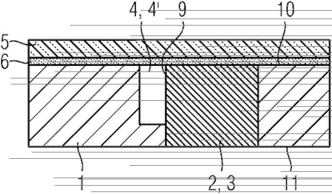
[0035] For a better understanding of fluid flow control devices, the figure 1 An example of a valve is shown in . This valve consists of a plastic base body 1 and an elastomeric substance 2 . Substrate 1 is meant to be a support or substrate and can be in the form of a chip card in which an array of electrochemical sensors is arranged on embedded chips for the detection of biochemical substances. For the sake of simplicity, the design of the chip card should not be described in detail here. An embodiment without a chip card is also possible, for example in an optical analysis device.

[0036] A first recess 4 is formed in the base body 1 . The first groove 4 opens in the direction of the front side 10 of the base body 1 . It has the shape of a channel and serves as a flow channel 4'. Liquid or gas can flow through the flow channel 4'. Immediately adjacent to the first groove 4 , a second groove 3 adjoining the flow channel is formed. It has a common boundary surface wit...


PUM


Abstract

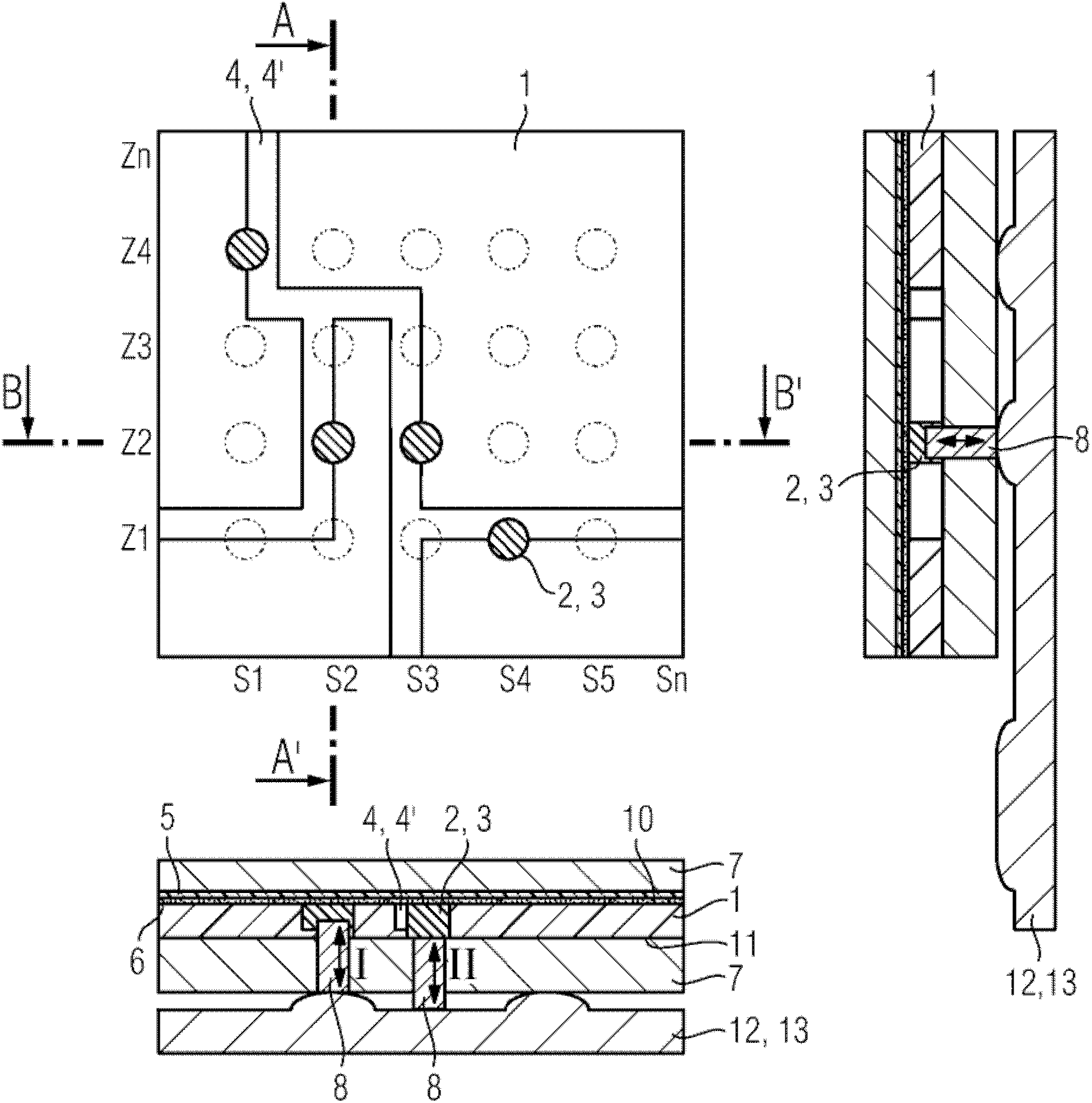
The present invention relates to a device for controlling fluid flow in a lab-on-a-chip system. It has an array of valves arranged in n columns Sn and m rows Zm and each designed to control the fluid flow in the associated flow channel (4). The array comprises at least two valves, wherein each column Sn has at most one valve and each row Zm has between 0 and n valves. An actuating device (13) for actuating the valve is provided. The valve is actuated by pressure. To manufacture the device, the flow channels (4) are arranged according to the layout of the valves.

Description

technical field [0001] The invention relates to a device for controlling fluid flow in a Lab-on-a-Chip-Systeme (Lab-on-a-Chip-Systeme), comprising an array of valves. The valves are arranged in n columns S n and m row Z m , where n and m are integers. They are each designed to control the fluid flow in the associated flow channel. Furthermore, the device has an actuating device for the valve. A device having the above-mentioned features is known, for example, from EP0180064B1. Furthermore the invention relates to a method of controlling fluid flow in such a lab-on-a-chip system and a method of manufacturing the device. Background technique [0002] Lab-on-a-chip systems are used in biosensing technology to enable parallel biochemical analyses. On a substrate consisting, for example, of a plastic card, the microfluidic device and the chip comprising the sensor array are integrated. Sensor arrays consist, for example, of electrochemical sensors arranged in rows and colu...

Claims


Application Information

Patent Timeline
Patent Type & Authority Patents(China)
IPC IPC(8): B01L3/00G01N35/10F16K99/00
CPCB01L2300/123B01L2300/0816F16K99/0015B01L3/502738F16K99/0001G01N2035/00237G01N35/1097F16K2099/008G01N2035/00158F16K2099/0084F16K99/0042Y10T137/0396B01L2400/0655Y10T137/86919Y10T137/87Y10T137/86445F16K11/065F16K31/52483B01L2400/0661F16K27/003F16K7/16F16K11/161B01L2300/0636B01L2400/06B01L2400/082
Inventor W.古姆布莱克特K.弗雷德里克P.保里卡
Owner BOEHRINGER LNGELHEIM VETMEDICA GMBH
Learn More