Spot light source and bulb-type light source

A point light source and halogen bulb technology, applied in the field of point light source and bulb-shaped light source, can solve the problem that LED lighting devices are not suitable for halogen bulbs, and achieve the effect of improving heat dissipation efficiency and high thermal conductivity

Inactive Publication Date: 2012-05-09
PANASONIC CORP
View PDF10 Cites 5 Cited by
  • Summary
  • Abstract
  • Description
  • Claims
  • Application Information

AI Technical Summary

Problems solved by technology

Therefore, such LED lighting fixtures are not suitable as a replacement for existing halogen bulbs in a way that actively utilizes leaked light

Method used


Image

  • Spot light source and bulb-type light source
  • Spot light source and bulb-type light source
  • Spot light source and bulb-type light source

Examples


Embodiment Construction

[0073] Embodiments of the present invention will be described in detail with reference to the drawings.

[0074] figure 1 It is a partially cutaway view showing the structure of the point light source according to the embodiment of the present invention.

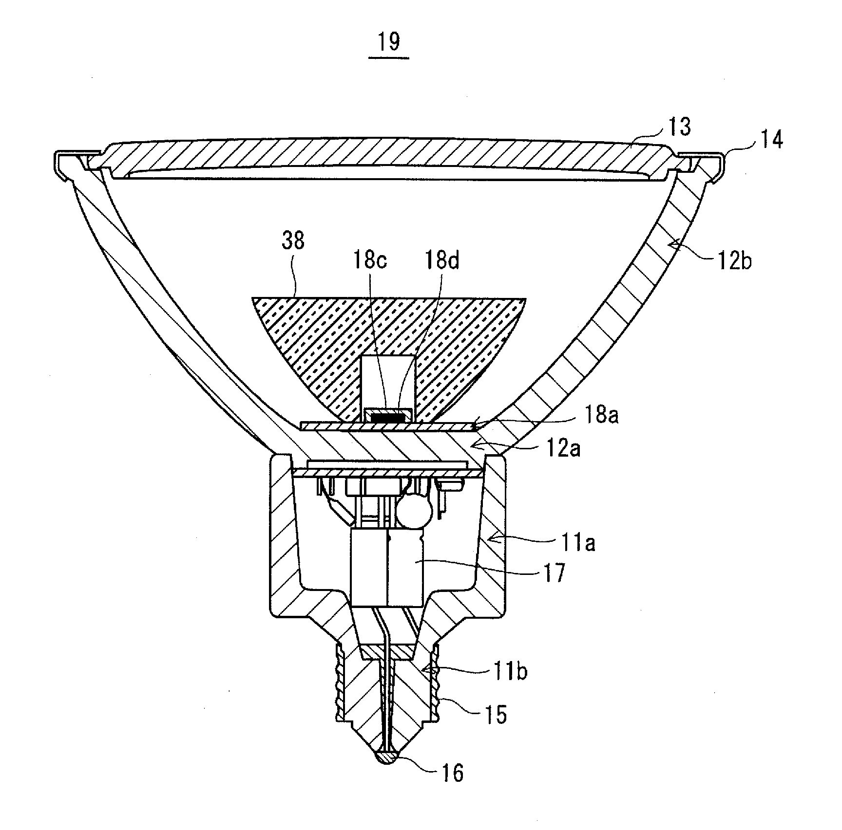
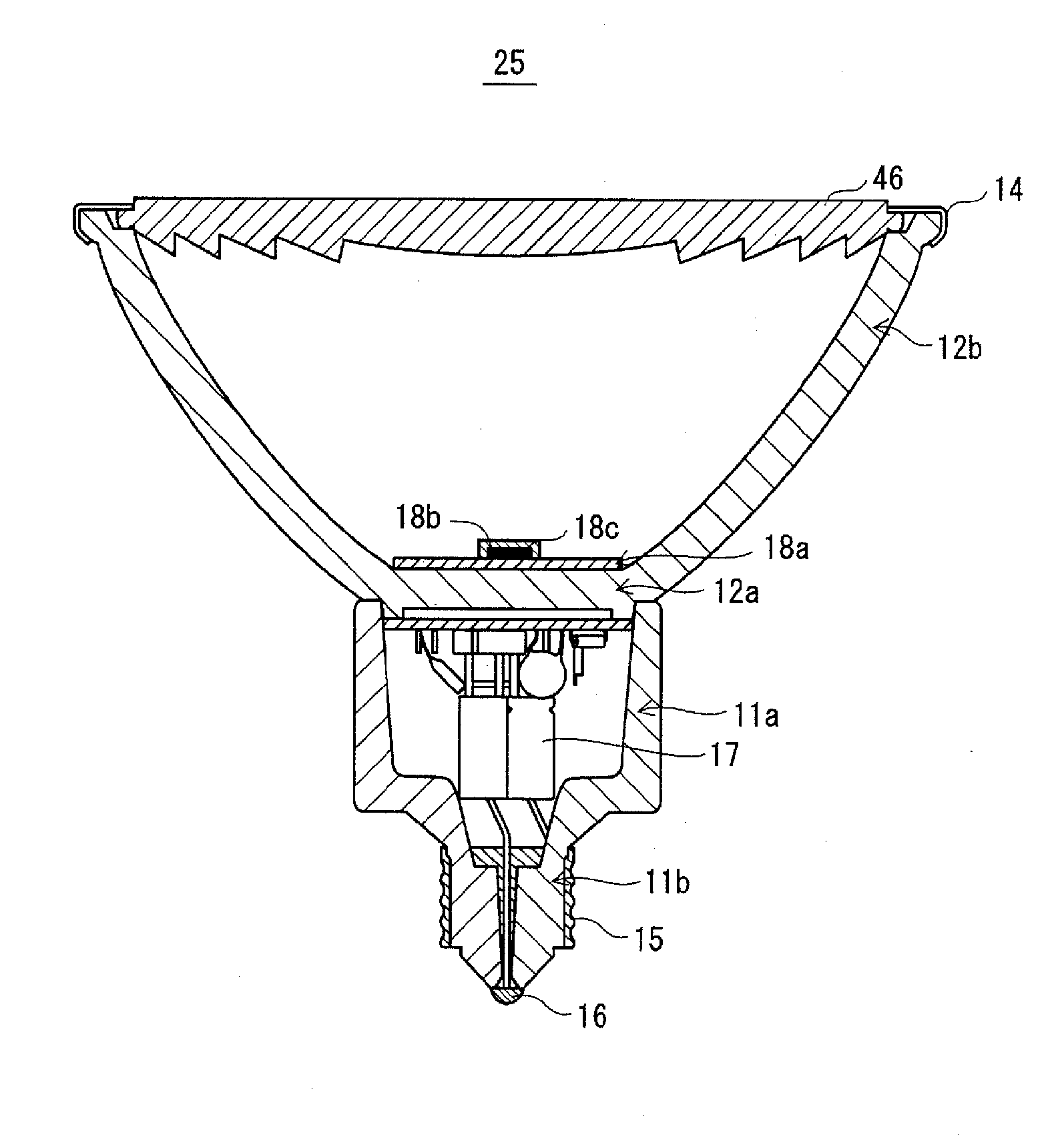
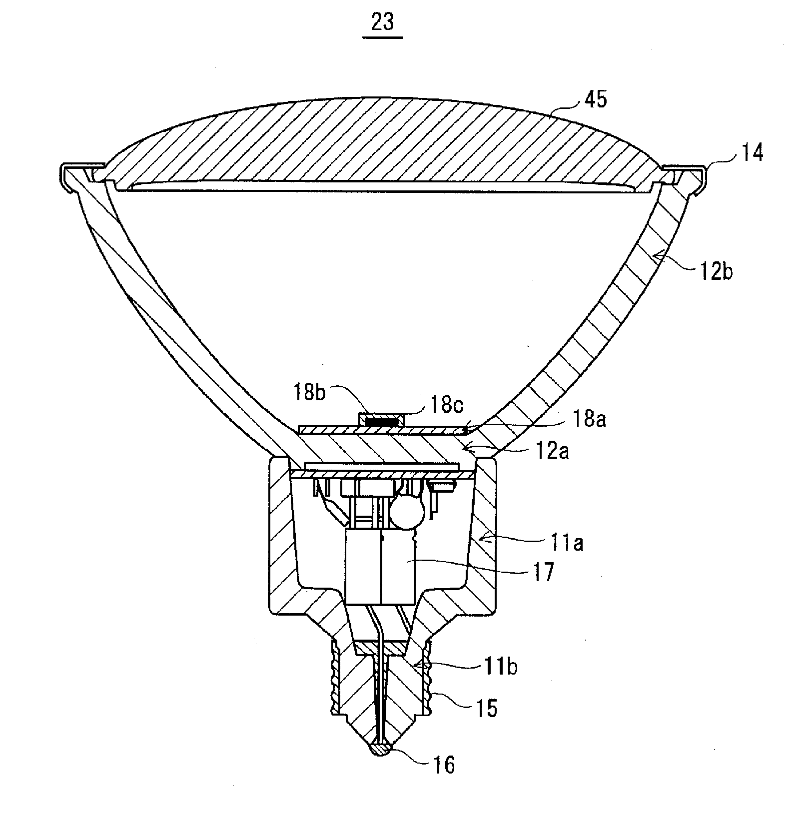
[0075] The main structure of the point light source 1 includes a housing 11 , a heat sink 12 and a light emitting part 18 . First, the schematic structure of these components will be described, and then the detailed structure of the heat sink 12 will be described.

[0076]

[0077] The housing 11 is made of an insulating material such as ceramics, and includes a cylindrical portion 11a and a protrusion 11b extending from one end of the cylindrical portion 11a. A lighting circuit 17 is housed in the inner space of the cylindrical portion 11a. A metal shell 15 is provided on the outer peripheral surface of the protruding portion 11b, and a metal eyelet 16 is provided on the front end portion of the protruding portion 11b....


PUM


Abstract

Disclosed is a spot light source (1) comprising a case (11), a heat radiator (12) and a light-emitting unit (18). In the spot light source (1), the heat radiator (12) is formed in a bowl-like shape by a bottom part (12a) and a side part (12b) that extends from the outer edge of the bottom part (12a), and the side part (12b) is composed of a light-permeable ceramic material. Outgoing light from an LED element (18b) that is provided in the light-emitting unit (18) is guided toward the side part (12b) by means of a lens (18d) to generate leak light to the side of the spot light source (1), whereby high decorative performance can be created.

Description

technical field [0001] The present invention relates to a point light source and a light bulb-shaped light source having a light emitting element such as an LED (Light Emitting Diode: Light Emitting Diode). Background technique [0002] Halogen bulbs with reflectors are widely used as point light sources such as spotlights in commercial facilities and residences. [0003] In addition, power saving and long life are also emphasized in the field of lighting, and a technology for replacing existing light bulbs with lighting devices having LEDs (hereinafter referred to as LED lighting devices) has been researched and developed. The halogen light bulb with a reflector is no exception, and many LED lighting devices with a reflector have been proposed (for example, refer patent document 1, 2). [0004] Generally, LEDs have the characteristic that heat is generated during the lighting process, and the higher the temperature due to the heat, the lower the luminous efficiency. There...

Claims


Application Information

Patent Timeline
Patent Type & Authority Applications(China)
IPC IPC(8): F21S2/00F21V7/00F21V7/22F21V29/00F21Y101/02F21V29/505
CPCF21Y2101/02F21V29/20F21K9/00F21W2121/00F21V5/045F21K9/137F21K9/135F21V13/04F21K9/50F21V29/70F21V29/86F21K9/232F21K9/233F21K9/60F21Y2115/10
Inventor 川越进也桥本尚隆小岛敏靖东昌范
Owner PANASONIC CORP
Why Eureka
Try Eureka