
Method for liquefying a hydrocarbon-rich stream

A technology for liquefied, hydrocarbon-rich fractions, applied in liquefaction, refrigeration and liquefaction, irreversible cycle compression machines, etc., can solve the problem of targeted adjustment and adjustment of temperature curves, the possibility of intervention or the number of degrees of freedom limited, etc. question

Active Publication Date: 2012-05-09
LINDE AG
View PDF6 Cites 6 Cited by
  • Summary
  • Abstract
  • Description
  • Claims
  • Application Information

AI Technical Summary

Problems solved by technology

The disadvantage is that the liquid phase of the cooling medium can only evaporate at one pressure level
Targeted regulation and adjustment of the desired temperature profile is therefore difficult, since the intervention possibilities or the number of degrees of freedom are limited in such processes

Method used


Image

  • Method for liquefying a hydrocarbon-rich stream
  • Method for liquefying a hydrocarbon-rich stream
  • Method for liquefying a hydrocarbon-rich stream

Examples


Embodiment Construction

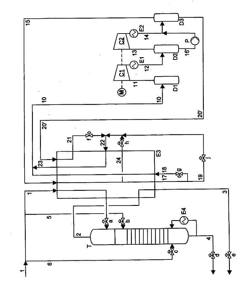
[0013] The following is explained figure 2 The examples shown in are only described with figure 1 The difference between the methods shown in .

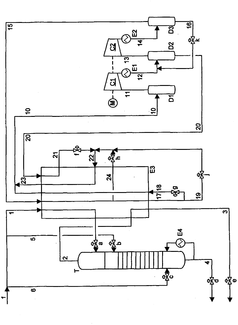
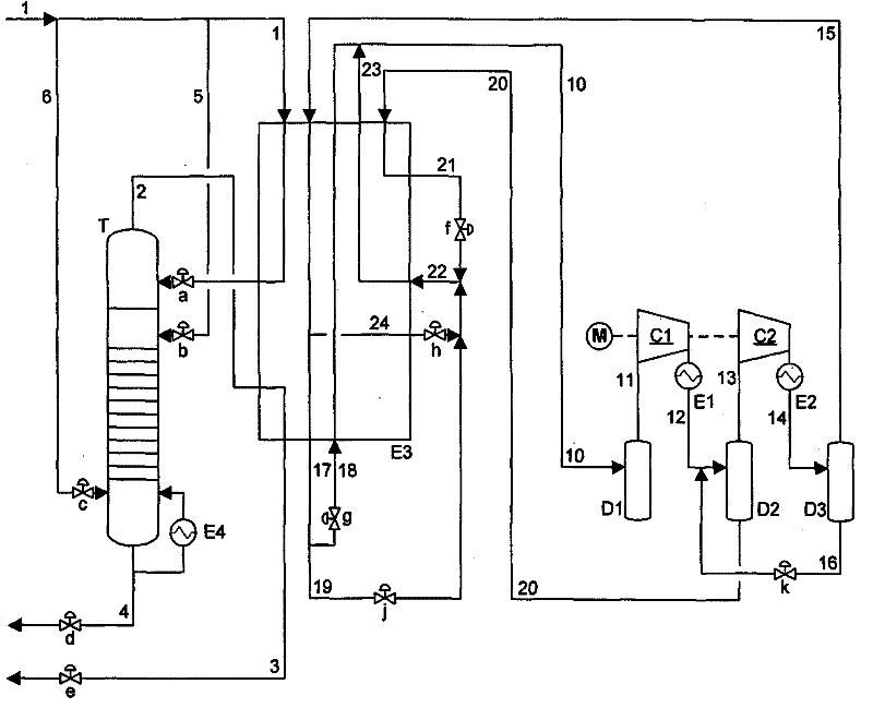
[0014] The process of the present invention for liquefying hydrocarbon-rich fractions is figure 1 and 2 The embodiment shown in has a separation column T for separating the rich C 2+ The fraction is separated from the hydrocarbon-rich fraction to be liquefied. The fraction to be liquefied is referred to below as the natural gas stream and is supplied via line 1 to the multi-stream heat exchanger E3.

[0015] The multi-flow heat exchanger is preferably designed as a welded aluminum plate heat exchanger. Depending on the size of the plant, preferably 1 to 6 heat exchanger units are arranged in parallel. Alternatively, the multi-flow heat exchanger E3 can also be designed as a wound heat exchanger. Here, the aluminum plate heat exchanger is preferably used for a liquefaction capacity of 30,000 to 500,000 tons of LNG per year, an...


PUM


Abstract

A method for liquefying a hydrocarbon-rich fraction and simultaneously separating a C2+-rich fraction is described. In said method, the hydrocarbon-rich fraction is cooled and liquefied by indirectly exchanging heat with the coolant mixture of a coolant mixture cycle in which the coolant mixture is condensed in at least two stages, and the C2+-rich fraction is separated at an adjustable temperature level, wherein the coolant mixture is separated into a gaseous and a liquid fraction, and both fractions are supercooled, are expanded essentially to the initial pressure of the first condenser stage, and are at least partially evaporated. According to the invention, at least a partial stream (19, 24) of the liquefied, previously gaseous fraction of the coolant mixture (15) is at least temporarily expanded (j, h) and admixed to the expanded liquid fraction of the coolant mixture (21).

Description

technical field [0001] The present invention relates to a method for separating rich C 2+ Process for the simultaneous liquefaction of hydrocarbon-rich fractions, wherein the cooling and liquefaction of the hydrocarbon-rich fraction takes place under indirect heat exchange with a cooling medium mixture of a cooling medium mixture circulation circuit and is rich in C 2+ The separation of the fractions takes place at an adjustable temperature level, the cooling medium mixture is compressed in at least two stages in the cooling medium mixture circuit, wherein the cooling medium mixture is divided into a gaseous and a liquid fraction, two Both fractions are cooled, expanded substantially to the suction pressure of the first compressor stage and at least partially vaporized. Background technique [0002] A process of this type for liquefying hydrocarbon-rich fractions is known, for example, from DE-A 197 22 490 . Such a liquefaction method is used, for example, when liquefying ...

Claims


Application Information

Patent Timeline
IPC IPC(8): F25J1/02
CPCF25J3/0209F25J1/0262F25J3/0238F25J2215/04F25J2200/02F25J2270/902F25J2210/06F25J1/0291F25J2200/70F25J2270/18F25B9/006F25J1/0055F25J1/0212F25J2280/02F25J1/0022F25J1/0244F25J2245/02F25J3/0233F25J2270/66F25B1/10
Inventor H·鲍尔R·扎佩尔D·加尔特
Owner LINDE AG
Learn More