
Monitoring method and monitoring apparatus for machine tool, and machine tool

A technology for monitoring devices and machine tools, which is applied in metal processing mechanical parts, measuring/indicating equipment, program control, etc., and can solve the problem that the relationship between rotation speed and vibration is difficult to understand, the stable critical map is difficult to agree, and the regeneration of flutter may not be stable. Issues such as criticality

Active Publication Date: 2012-05-16
OKUMA CORP
View PDF6 Cites 28 Cited by
  • Summary
  • Abstract
  • Description
  • Claims
  • Application Information

AI Technical Summary

Problems solved by technology

Therefore, it is necessary to display the actual machining value on the Campbell diagram to judge the chattering state. When checking the rotation speed, it is difficult to understand the relationship between the rotation speed and the magnitude of the vibration.
[0010] On the other hand, the method of Non-Patent Document 1 is effective for regenerative chatter, but assuming that the chatter of the end mill tool is completely iso-mode, it may not be possible to calculate the stability criticality of regenerative chatter under all machining conditions with high accuracy.
However, for operators with poor chatter knowledge, it is difficult to judge the stability critical line graph under the actual processing conditions only by looking at the stable critical line graph.

Method used


Image

  • Monitoring method and monitoring apparatus for machine tool, and machine tool
  • Monitoring method and monitoring apparatus for machine tool, and machine tool
  • Monitoring method and monitoring apparatus for machine tool, and machine tool

Examples


Embodiment Construction

[0030] Embodiments of the present invention will be described below based on the drawings.

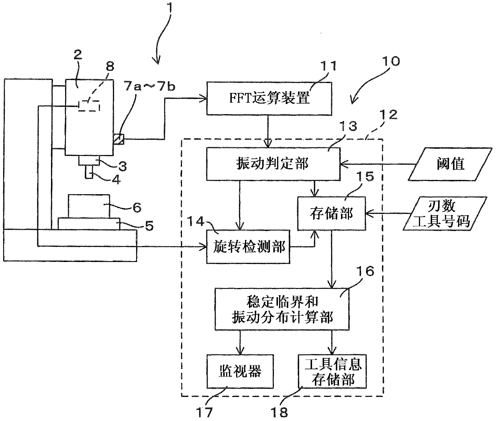
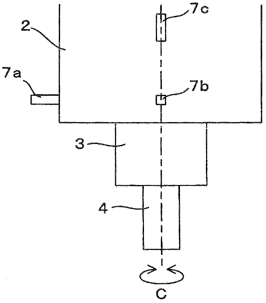
[0031] figure 1 This is a schematic configuration diagram of a vertical machining center as an example of a machine tool. A vertical machining center 1 is provided with a spindle 3 rotatably around a C-axis on a spindle head 2 provided above, and a tool 4 attached to the spindle 3, In this known structure, the workpiece 6 provided on the lower processing table 5 is processed, and the numerical control device 12 provided in the monitoring device 10 described later controls the rotation of the main shaft 3 according to a numerical control (NC) program, and through The illustrated automatic tool changer is capable of automatically changing the tool 4 .

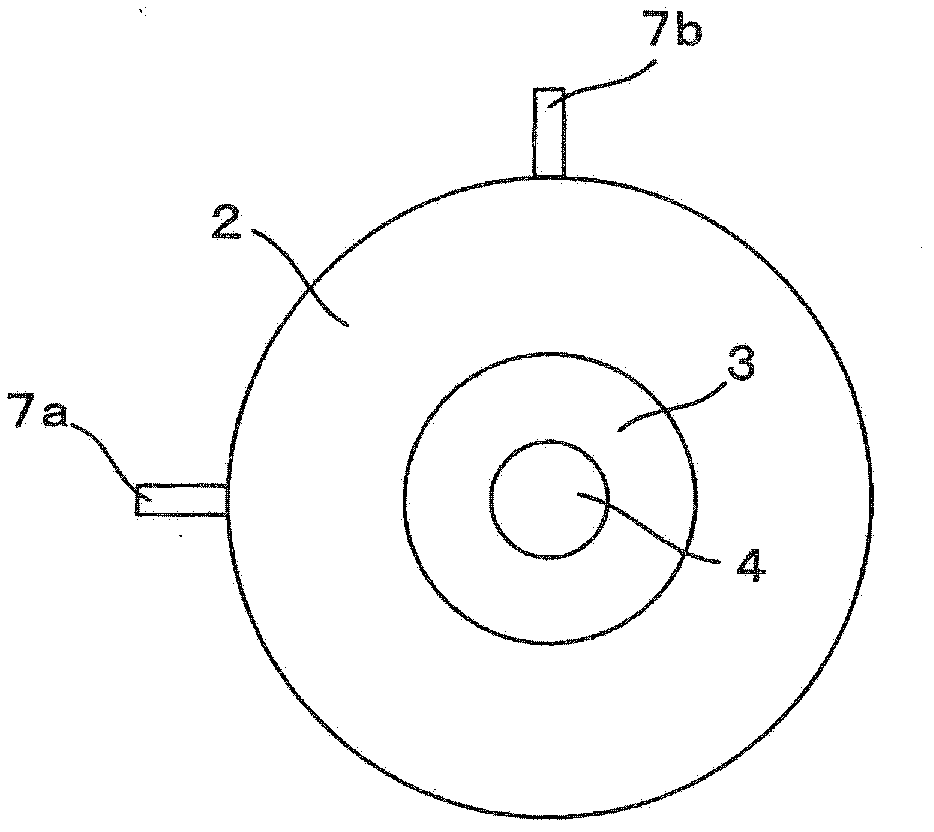
[0032] The monitoring device 10 is provided with an FFT computing device (Fast Fourier Transform: Fast Fourier Transform computing device) 11 and a numerical control device 12 . The vibration sensors 7a to 7c are connected to the FFT co...


PUM


Abstract

The monitoring apparatus includes vibration sensors that detect vibration accompanying machining, a rotation detector and a rotation detection section that detect rotation of a main spindle, and a stability limit and vibration distribution calculation section that creates, on the basis of vibration information obtained from the vibration sensors and a rotation speed of the main spindle detected by the rotation detector and rotation detection section, both a stability limit diagram illustrating a relationship between the rotation speed and a stability limit of the machining and a vibration distribution diagram illustrating a relationship between the rotation speed and the vibration, and displays the created diagrams on a monitor in a vertical arrangement.

Description

technical field [0001] The present invention relates to a monitoring method and a monitoring device for monitoring a machining state related to vibration in a machine tool that performs machining while rotating a tool or workpiece attached to a spindle, and a machine tool having the same. Background technique [0002] In machine tools such as machining centers that perform machining while rotating a tool or workpiece attached to the main shaft, it is known that chatter occurs due to machining conditions such as the rotational speed or feed speed of the main shaft, which deteriorates the machined surface, or The tool suffers damage which also leads to a deterioration in the life of the tool. [0003] However, regarding the processing conditions such as the rotational speed at the time of the initial processing, it is nothing more than searching based on experience and trial and error. The operator records the processing conditions during the trial and error process, and read...

Claims


Application Information

Patent Timeline
Patent Type & Authority Applications(China)
IPC IPC(8): B23Q17/12B23Q17/10
CPCB23Q17/12B23Q17/007G05B2219/37435Y10T408/21
Inventor 安藤知治上野浩浜口显秀
Owner OKUMA CORP
Learn More