Yarn winding apparatus

A yarn winding machine and yarn winding technology, which can be applied to spinning machines, intermittently wound spinning machines, textiles and papermaking, etc., can solve problems such as increased cost and complicated replacement operations.

Active Publication Date: 2012-05-16
MURATA MASCH LTD
View PDF10 Cites 9 Cited by
  • Summary
  • Abstract
  • Description
  • Claims
  • Application Information

AI Technical Summary

Problems solved by technology

Therefore, complicated replacement work is required, or the cost inc...

Method used


Image

  • Yarn winding apparatus
  • Yarn winding apparatus
  • Yarn winding apparatus

Examples


Embodiment Construction

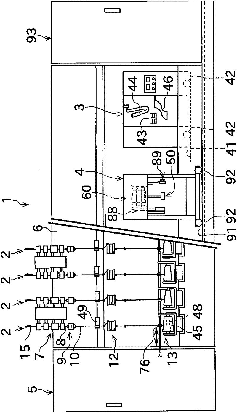
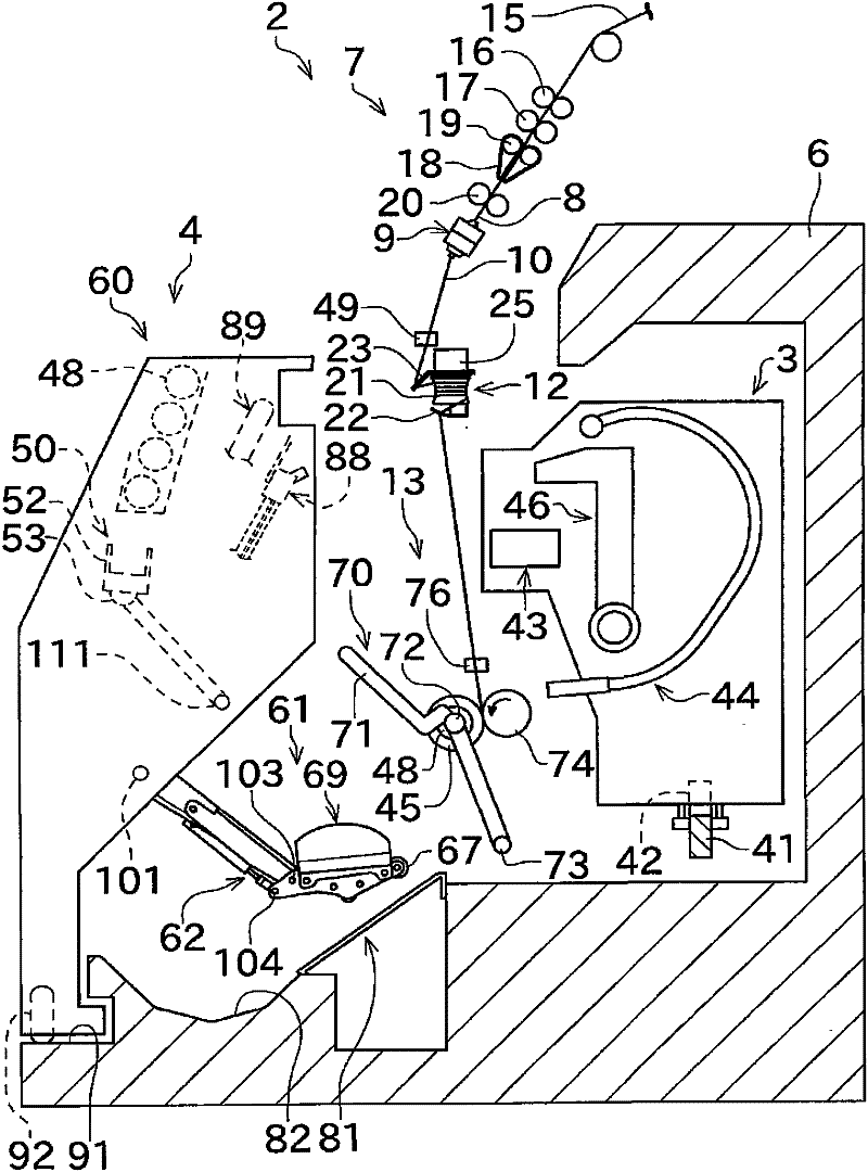
[0036] Next, a spinning frame (winding frame) according to an embodiment of the present invention will be described with reference to the drawings. In addition, "upstream" and "downstream" in this specification mean upstream and downstream in the traveling direction of the yarn during spinning. figure 1 It is a front view showing the overall structure of the spinning frame 1. figure 2 It is a longitudinal sectional view of the spinning frame 1.

[0037] figure 1 The illustrated fine spinning machine 1 as a winding machine includes a plurality of spinning units (winding units) 2 arranged in parallel. The spinning frame 1 includes: a piecing cart 3 , a doffing cart 4 , a blower box 93 , and an engine box 5 .

[0038] Such as figure 1 As shown, each spinning unit 2 includes, as a main structure, a draft device 7, a spinning device 9, a yarn storage device 12, and a winding device 13 arranged in the following order from upstream to downstream. The draft device 7 is provid...


PUM


Abstract

A bobbin installation device (60) includes a bobbin gripping section (52) and a path adjusting plate (59). A pivot arm (58) is attached to a rocker shaft (111) and swings by pivoting about the rocker shaft (111). The bobbin gripping section (52) grips a bobbin, onto which a yarn is to be wound, and supplies the bobbin in between a pair of bobbin holders (72) that define a target position of the bobbin. The path adjusting plate (59) can adjust a path (bobbin supplying path) along which the bobbin is supplied by the bobbin gripping section (52) to the target position.

Description

technical field [0001] The present invention mainly relates to a yarn winding machine provided with a bobbin setting device for setting a bobbin for winding a yarn at a target position. Background technique [0002] Conventionally, there is known a bobbin setting device that supplies a bobbin with unwound yarn at the start of the yarn winding operation by the spinning machine, after discharging a full package from the spinning machine, etc. to the bobbin holding section of the spinning machine, etc., to make preparations for starting the winding operation (bunch winding, etc.). Japanese Patent Application Laid-Open No. 2005-219880 and Japanese Patent Laid-Open No. 9-100066 disclose spinning machines equipped with such bobbin setting devices. [0003] A doffing cart included in the spinning machine disclosed in JP 2005-219880 A is provided with a clamper (bobbin holding unit) for holding a bobbin. The doffing cart can supply the bobbin to the cradle by rotating the gripper ...

Claims


Application Information

Patent Timeline
IPC IPC(8): D01H9/18D01H3/16
CPCB65H54/26B65H2701/31B65H54/88B65H67/0417
Inventor 盐田健
Owner MURATA MASCH LTD
Why Eureka
Try Eureka