Blade of a wind turbine

A technology for wind turbines and blades, which is applied in the field of wind turbine blades, can solve problems such as the inability to adjust blade vortex generators, and achieve the effect of increasing the bonding surface

Active Publication Date: 2012-05-16
SIEMENS GAMESA RENEWABLE ENERGY AS
View PDF7 Cites 7 Cited by
  • Summary
  • Abstract
  • Description
  • Claims
  • Application Information

AI Technical Summary

Problems solved by technology

[0015] In this case the vortex generators are fixed for the entire life of the blade, but the vortex generators on the surface of the blade cannot be adjusted even if needed later

Method used


Image

  • Blade of a wind turbine
  • Blade of a wind turbine
  • Blade of a wind turbine

Examples


Embodiment Construction

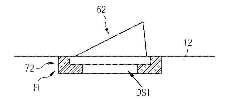
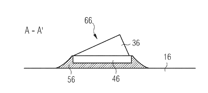
[0040] figure 1 A preferred arrangement according to the invention is shown.

[0041] The vortex generator 61 includes a platform 41 and an extension 31 .

[0042] The platform serves as the base or bottom of the extension 31 .

[0043] The extension 31 may preferably be shaped like a fin.

[0044] The platform 41 of the vortex generator 61 is arranged in the recess 71 .

[0045] The recess 71 is integrally formed as part of the blade 11 and may be formed and shaped into the blade 11 when manufacturing the blade.

[0046] The recess 7 can be milled uniformly into the blade 11 later, for example at a wind turbine location.

[0047] The connecting portion 51 is arranged to fix the platform 41 into the recess 71 . This can be done using adhesive, glue, silicone or double sided tape with adhesive.

[0048] The surface of the platform 41 and the inner surface of the recess 71 may even be shaped to interact to achieve a fixed mechanical connection.

[0049] A well-known stru...


PUM


Abstract

A blade of a wind turbine is provided with at least one vortex-generator, which is positioned at the blade-surface. The vortex-generator is constructed and arranged in a way that it contributes to the aerodynamic characteristics of the blade. The vortex-generator comprises a platform and an extension-part. The blade contains a recess, which is constructed and arranged to receive at least a part of the platform of the vortex-generator. The platform is fixed within the recess.

Description

technical field [0001] The invention relates to a blade of a wind turbine and a method of retrofitting the blade. Background technique [0002] It is known that the use of certain shaped devices can create beneficial vortices in the vicinity of the blades of wind turbines. These devices are known as "vortex generators". [0003] Vortex is used to affect the air flow along the surface of the wind turbine blade. For example, vortex generators are used to counteract the stall of air along the blade. Thus, the rotational movement of the blade is improved by the generator. [0004] WO 0015961 A1 discloses a wind turbine blade provided with a plurality of vortex generators. A plurality of vortex generators protrude from the leeward side of the blade and are used to control the so-called "boundary layer separation". [0005] WO 2008113350 discloses an advantageous design of a wind turbine blade. The blades show one or more parallel rows of sub-boundary layer vortex generators...

Claims


Application Information

Patent Timeline
Patent Type & Authority Applications(China)
IPC IPC(8): F03D11/00
CPCF05B2230/60Y02E10/722F03D1/0608F05B2230/80F03D1/065Y02E10/721F05B2240/122F05B2240/3062Y02E10/72Y10T29/49337Y02P70/50F05B2240/30
Inventor J.J.O.克里斯滕森C.特鲁
Owner SIEMENS GAMESA RENEWABLE ENERGY AS
Why Eureka
Try Eureka