Direct-current motor based on specific electric brush installation angle

An installation angle, DC motor technology, applied in electromechanical devices, DC commutators, electrical components, etc., can solve the problem of poor contact between brush blades and commutators, wear of brush blades and commutator, and brush blades Large installation angle and other problems can reduce the probability of bursting, eliminate the accumulation of wear debris, and improve the effect of arc resistance.

Inactive Publication Date: 2012-05-16
HUBEI HUIDIAN TECH CO LTD
View PDF4 Cites 0 Cited by
  • Summary
  • Abstract
  • Description
  • Claims
  • Application Information

AI Technical Summary

Problems solved by technology

This angle is generally between 32-42 degrees. If the installation angle of the brush piece is too large, although the electrical contact performance is improved, it will cause rapid wear of the brush piece and the

Method used


Image

  • Direct-current motor based on specific electric brush installation angle
  • Direct-current motor based on specific electric brush installation angle
  • Direct-current motor based on specific electric brush installation angle

Examples


Embodiment Construction

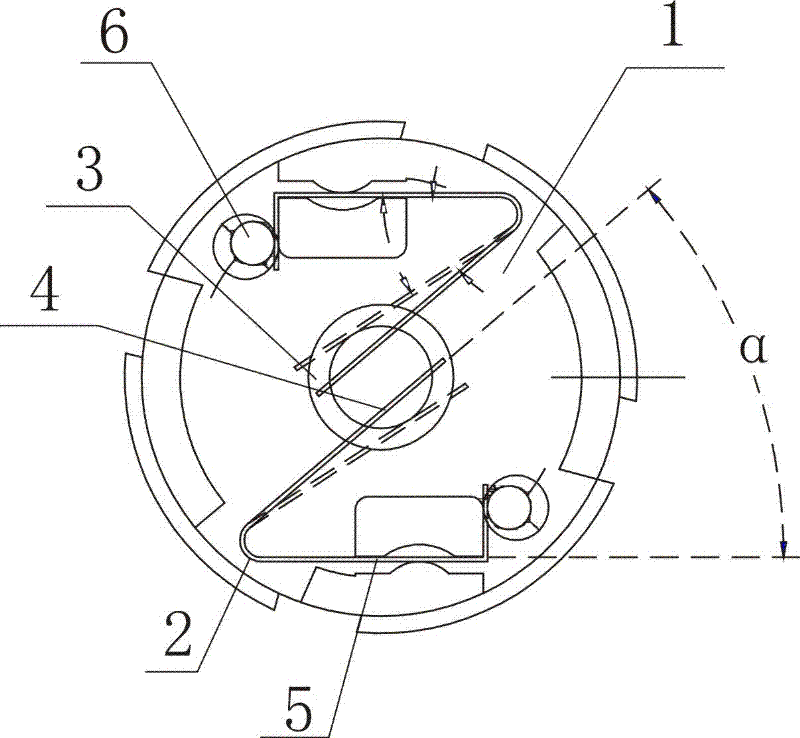
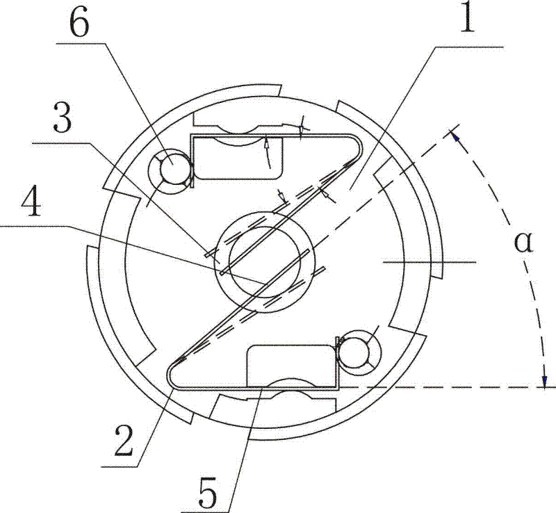
[0017] A DC motor based on a specific brush installation angle includes a motor 1 stator part and a rotor part, the motor 1 stator part is provided with a brush device 2, the motor 1 rotor part is provided with a reversing device 3, and the brush head 4 of the brush device 2 is connected to the Sliding contact of reversing device 3;

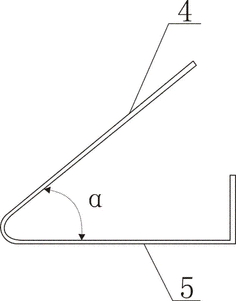
[0018] The included angle α between the brush head 4 and the brush handle 5 is 38°.

[0019] The welding spot 6 between the brush handle 5 and the lead wire of the motor 1 is formed by automatic welding.

[0020] The commutation piece and the brush head 4 of the reversing device 3 are plated with rare earth materials.

[0021] Implementation steps:

[0022] ①. The brush head 4 and the brush handle 5 of the brush device 2 are formed by bending an elastic metal sheet in advance, such as figure 2 As shown, the angle α between the brush head 4 and the handle 5 formed after bending is 38°. The brush device 2 is embedded in the motor 1 and has a c...


PUM


Abstract

The invention relates to a direct-current motor based on a specific electric brush installation angle, which comprises a motor stator part and a rotor part, wherein the motor stator part is provided with a brush gear; the motor rotor part is provided with a reversing device; a brush head of the brush gear is in slide contact with the reversing device; and an included angle alpha between the brush head and a brush handle is 38 degrees. A welding spot of the brush head and a lead wire of the motor is formed through automatic welding, and rare earth materials are plated on reversing pieces of the reversing device and the brush head. According to the direct-current motor based on a specific electric brush installation angle, which is provided by the invention, the rare earth materials are plated on the reversing pieces of the reversing device and the brush head, so that the arc resistance of a reverser of a micromotor is improved, a main wear mechanism is converted from adhesive wear to abrasive wear, the phenomenon of abrasive dust collection in a groove is eliminated, and the reliability and the service life of the motor are remarkably improved; an automatic welding manner is adopted for the brush head and the lead wire of the motor, so that the probability of generation of crack of a plating layer of the motor is effectively reduced, and the manufacturing cost of the motor is reduced; and the included angle between the brush head and the brush handle selects an optimal angle, so that mechanical contact between the brush and the reversing device is favored, the mechanical loss is reduced to be minimum, the electrical contact performance is simultaneously improved, and the stability and the reliability of the product is improved.

Description

technical field [0001] The invention relates to a DC motor, in particular to a DC motor based on a specific brush installation angle. Background technique [0002] In most brushed DC motors, the brushes have brush wires (brush braids), and the current and voltage are introduced or drawn out by the action of the brushes and brush wires (brush braids). The brushes and commutator segments flow into the coils of the armature. However, in the process of brush welding, the phenomenon of brush coating bursting is often encountered. Some motor manufacturers are restricted by various factors (such as product scale, batch size, etc.), and instead of using automatic welding methods, they use traditional welding methods. Manual welding operation mode, so that if the brush coating bursts when welding the brush, it will cause damage to the operator's eyes, and after the brush coating bursts and falls off, the brush cannot continue to be used and is scrapped, resulting in an increase in m...

Claims


Application Information

Patent Timeline
IPC IPC(8): H02K13/10H02K23/00
Inventor 何雄宋秀琼
Owner HUBEI HUIDIAN TECH CO LTD
Why Eureka
Try Eureka