
Wheel suspension for the rear wheels of motor vehicles

A vehicle and suspension technology, applied in suspension, elastic suspension, steering mechanism, etc., can solve the problems of increased cost, complexity and consumption, and high cost

Inactive Publication Date: 2012-05-16
AUDI AG
View PDF7 Cites 13 Cited by
  • Summary
  • Abstract
  • Description
  • Claims
  • Application Information

AI Technical Summary

Problems solved by technology

It has major disadvantages: the overall axle construction itself is already very costly without the steering function
If steerability is required, the cost, complexity and expense will increase further

Method used


Image

  • Wheel suspension for the rear wheels of motor vehicles
  • Wheel suspension for the rear wheels of motor vehicles
  • Wheel suspension for the rear wheels of motor vehicles

Examples


Embodiment Construction

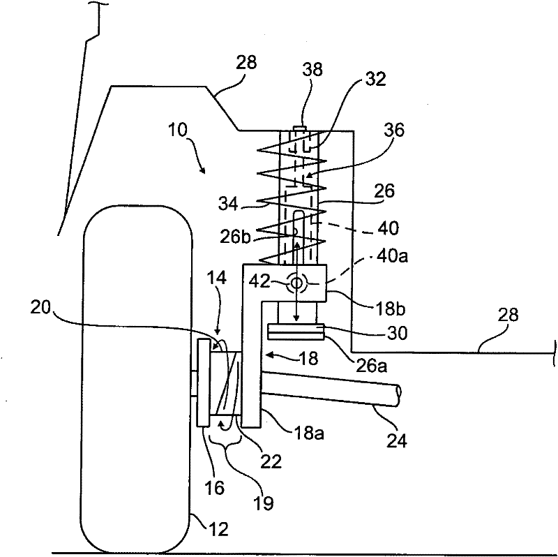
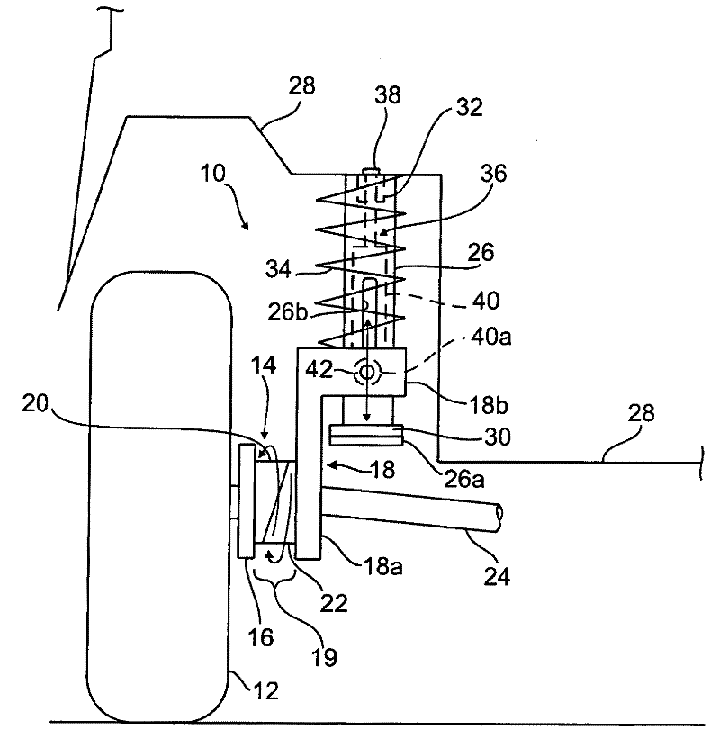
[0021] figure 1 The wheel suspension structure of a motor vehicle is marked with "10", the rear wheel 12 of which is rotatably supported on the wheel hub bracket 14.

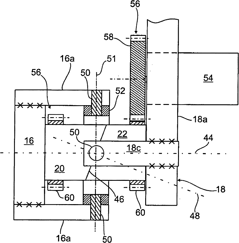
[0022] The multi-piece hub bracket 14 is composed of a carrier part 16 for receiving the wheel 12, a guide part 18 on the suspension side and an actuator 19 connected between the two. The actuator 19 has two rotating parts that can rotate relative to each other. Or adjust cylinders 20,22.

[0023] The guide element 18 has an approximately vertically extending section 18a through which a cardan shaft 24 (only partly shown) of the drive wheel 12 extends.

[0024] A sleeve-shaped section 18b protrudes approximately horizontally from the vertical section 18a of the guide element 18 toward the longitudinal center plane of the vehicle, and is guided displaceably on a tubular cylinder 26 as a linear guide.

[0025] The column 26 is fastened to the monocoque body 28 of the motor vehicle and has at its lower end an ann...


PUM


Abstract

The invention relates to a wheel suspension for motor vehicles, comprising a wheel carrier (14), which has a wheel-side carrier part (16) that rotatably supports a vehicle wheel (12) and an axle-side guide part (18), between which a control element is connected, wherein the wheel-side carrier part (16) can be swiveled about a swivel angle relative to the axle-side guide part (18) to set a toe angle and / or camber angle when said control element is actuated. According to the invention, the wheel carrier (14), in particular the guide part (18) thereof, is guided directly or indirectly on a body-fixed linear guide (26) in the form of a slotted guide so as to be able to move in the vertical direction.

Description

technical field [0001] The invention relates to a wheel suspension arrangement for a rear wheel of a motor vehicle according to the preamble of claim 1 . Background technique [0002] The driving dynamics of modern motor vehicles are mostly also influenced by the wheel suspension structure of the rear wheels, the control arms of which serve as wheel guide elements through their spatial position and through the elasticity of the control arm bearings to provide targeted driving characteristics, such as targeted Understeering trend etc. [0003] There are different technical solutions for the technical realization of such a rear axle steering structure of a (road) vehicle. Usually the tie rods are moved (steered) or their length is also changed. Furthermore, there are embodiments with split hub brackets as disclosed in US20020036385, WO199816418 or FR2884795. This split hub bracket is divided into a carrier part, a guide part and an actuator connected between the two. The ac...

Claims


Application Information

Patent Timeline
Patent Type & Authority Applications(China)
IPC IPC(8): B62D17/00B62D7/14B60G3/01B62D7/15B60G15/06
CPCB60G2204/129B60G2202/42B60G15/062B60G2200/445B60G2200/462B60G2200/46B60G2204/42B62D7/146B62D17/00B60G2200/10B60G3/01B60G2202/312B60G2204/62B60G2206/50
Inventor W·迈克尔H·穆勒K-H·梅廷格尔C·科西拉W·施密德
Owner AUDI AG
Learn More