
Anti-falling iron nail

An iron nail and anti-detachment technology, which is applied in the direction of nails, U-shaped nails, connecting components, etc., can solve the problems that affect the performance of wooden products and are easy to fall off

Inactive Publication Date: 2012-05-23
董金奎
View PDF0 Cites 0 Cited by
  • Summary
  • Abstract
  • Description
  • Claims
  • Application Information

AI Technical Summary

Problems solved by technology

However, because many existing woods are fast-growing woods, the material is relatively loose, and the iron nails driven in are relatively easy to fall off under external force due to the small holding force, which seriously affects the performance of wood products.

Method used


Image

  • Anti-falling iron nail
  • Anti-falling iron nail

Examples


Embodiment Construction

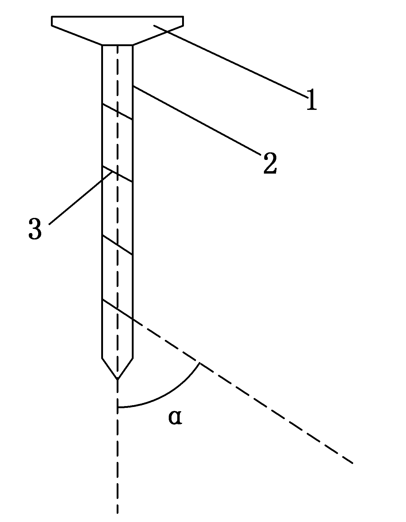
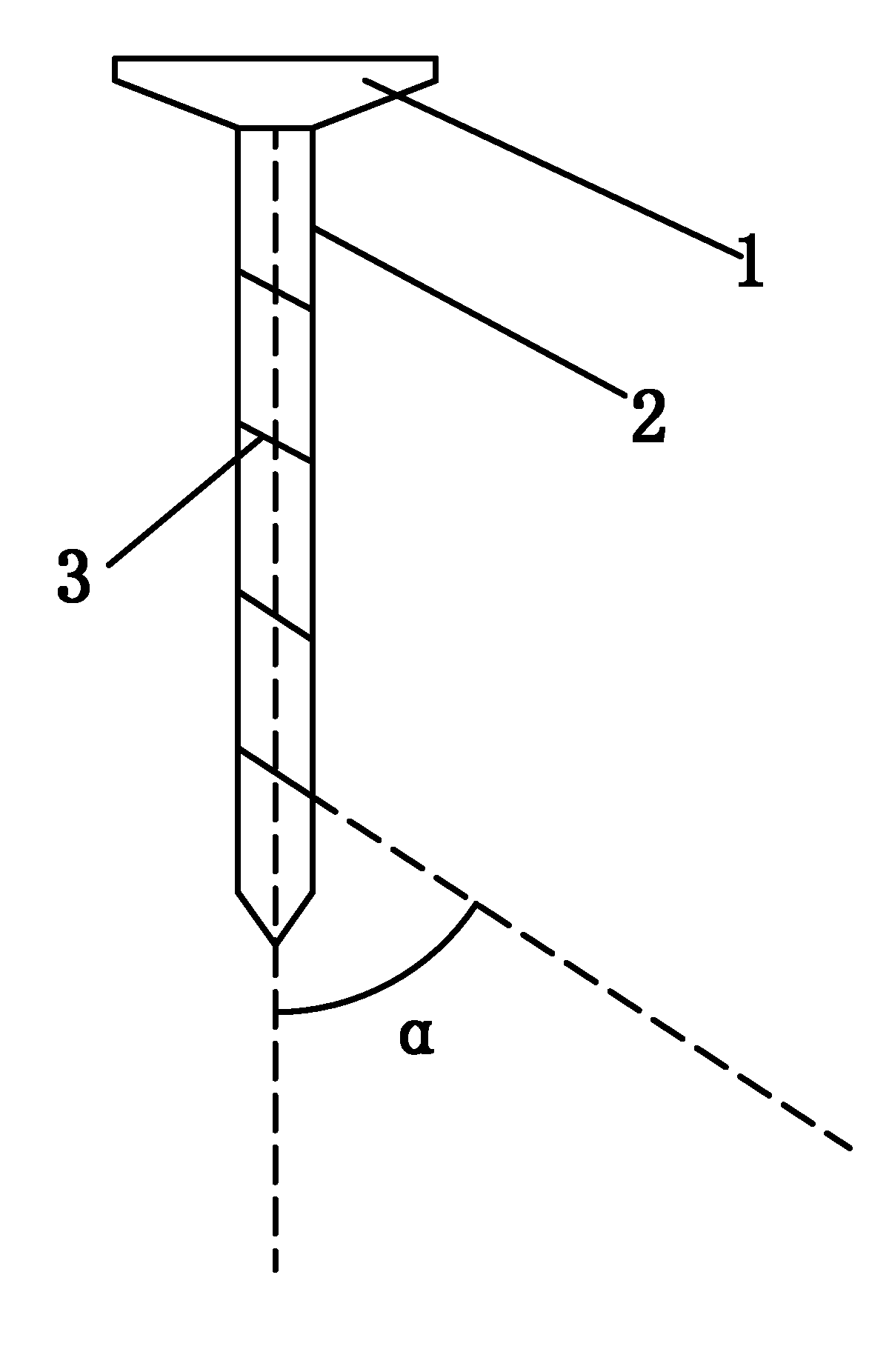
[0012] An anti-off iron nail, comprising a nail cap 1 and a nail body 2, characterized in that: the nail body 1 is provided with a row of fine grooves 3. The depth of the fine groove 3 is 0.2-0.5 mm. The fine groove 3 and the nail body 2 have an axial angle of 30°-45°. The distance between the fine grooves 3 is one-fifth of the length of the nail body 2 .

[0013] The preferred solution: a fall-off prevention iron nail, comprising a nail cap 1 and a nail body 2, characterized in that: the nail body 1 is provided with a row of fine grooves 3. The depth of the fine groove 3 is 0.3 mm. The fine groove 3 and the nail body 2 have an axial angle of 35° (∠α). The distance between the fine grooves 3 is one-fifth of the length of the nail body 2 . A layer of water-absorbing resin is coated in the fine groove 3 .

[0014] Usage method: before nailing into the anti-off iron nail of the present invention, soak the nail body 2 (all fine grooves 3 infiltration positions) with water, an...


PUM

PropertyMeasurementUnit
Depthaaaaaaaaaa

Abstract

The invention discloses an anti-falling iron nail, which comprises a nail cap (1) and a nail body (2). The anti-falling iron nail is characterized in that the nail body (2) is provided with a row of thin grooves (3). Connection strength of the anti-failing iron nail and wood is increased, and the iron nail can effectively avoid falling even when used for fast growing wood with loose quality.

Description

technical field [0001] The invention relates to an iron nail, in particular to an iron nail which prevents falling off from wooden materials. Background technique [0002] Iron nails are commonly used connecting parts in people's daily life, especially for connecting wooden materials to each other. However, because many existing woods are fast-growing woods, the material is relatively loose, and the iron nails driven in are relatively easy to fall off under external force due to the small holding force, which seriously affects the performance of wood products. Contents of the invention [0003] The object of the present invention is to provide an anti-falling nail, which can increase the connection force with wood, and can effectively prevent falling off when used for fast-growing wood with loose material. [0004] The technical solution of the present invention: a fall-off prevention iron nail, comprising a nail cap and a nail body, characterized in that: the nail body i...

Claims


Application Information

Patent Timeline
IPC IPC(8): F16B15/00
Inventor 董金奎
Owner 董金奎
Learn More