
Backlight module

A technology of backlight module and light source, applied in the field of backlight module, can solve the problem of not being able to keep the utilization efficiency of air gap light at the same time

Inactive Publication Date: 2012-05-23
CORETRONIC
View PDF7 Cites 3 Cited by
  • Summary
  • Abstract
  • Description
  • Claims
  • Application Information

AI Technical Summary

Problems solved by technology

However, none of the above-mentioned conventional designs can maintain the air gap and effectively improve the light utilization efficiency at the same time.

Method used


Image

  • Backlight module
  • Backlight module
  • Backlight module

Examples


Embodiment Construction

[0043] The aforementioned and other technical contents, features and effects of the present invention will be clearly presented in the following detailed description of the embodiments with reference to the drawings. The directional terms mentioned in the following embodiments, such as: up, down, left, right, front or back, etc., are only directions referring to the attached drawings. Accordingly, the directional terms are used to illustrate and not to limit the invention.

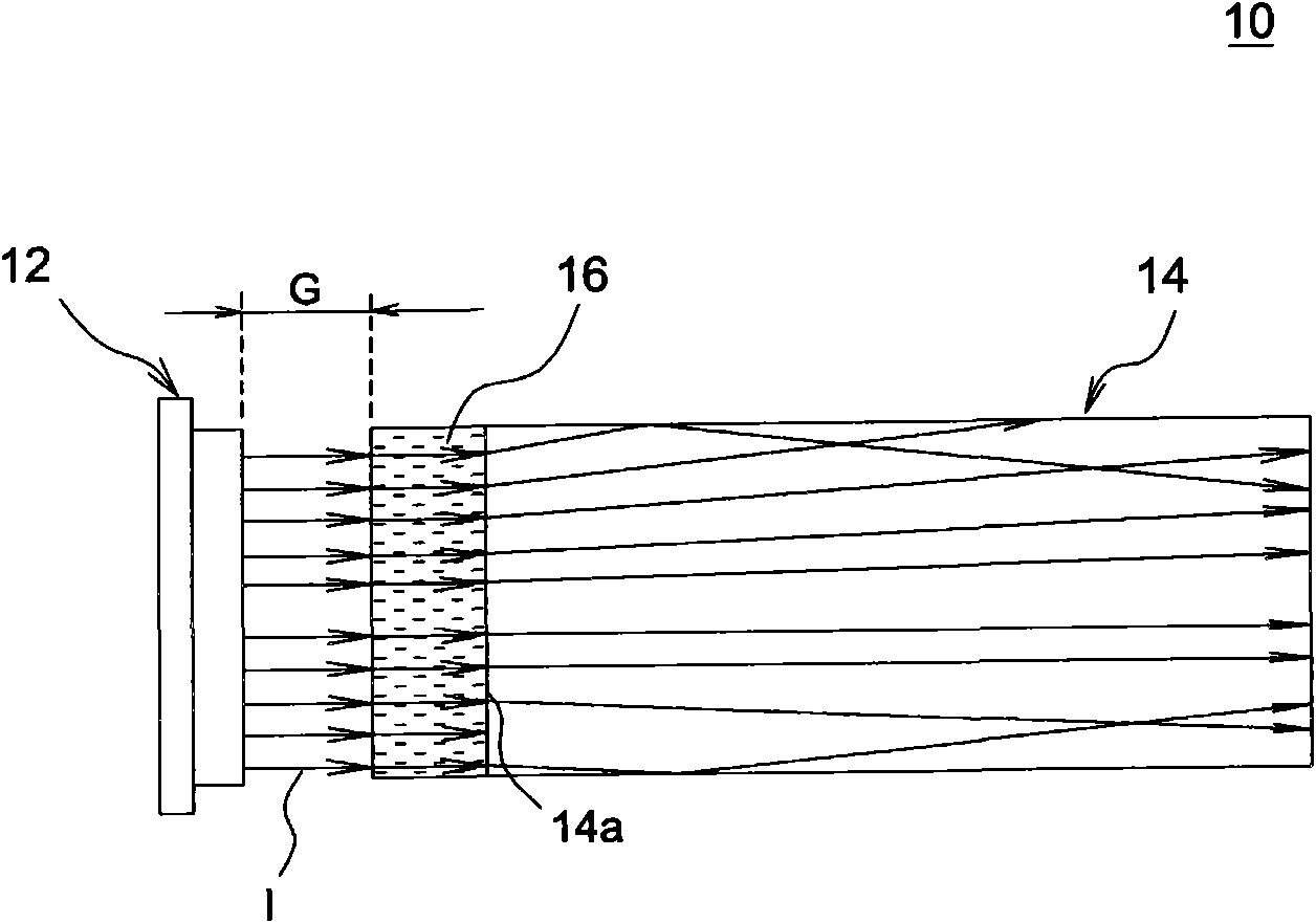
[0044] Figure 3A is a schematic top view of a backlight module according to an embodiment of the present invention, Figure 3B for Figure 3A A schematic side view of the backlight module. Please also refer to Figure 3A and Figure 3B , the backlight module 10 includes a light source 12 , a light guide plate 14 and a refraction medium 16 . The light source 12 can be, for example, an LED strip. The light guide plate 14 is suitable for guiding a light beam I provided by the light source 12 and at le...


PUM


Abstract

The invention discloses a backlight module. The backlight module comprises at least one light source, a light guide plate and a refractive medium. A light incidence surface of the light guide plate is adjacent to the light source, the refractive medium is adhered to the light incidence surface and an air gap is formed between the refractive medium and the light incidence surface, the refractive index of the refractive medium is smaller than the refractive index of the light guide plate, and the light beams which are emitted by the light source pass through the air gap and the refractive medium sequentially and then enter the light guide plate through the light incidence surface. The backlight module can effectively improve the light utilization rate, and can keep the air gap between the light guide plate and the light source.

Description

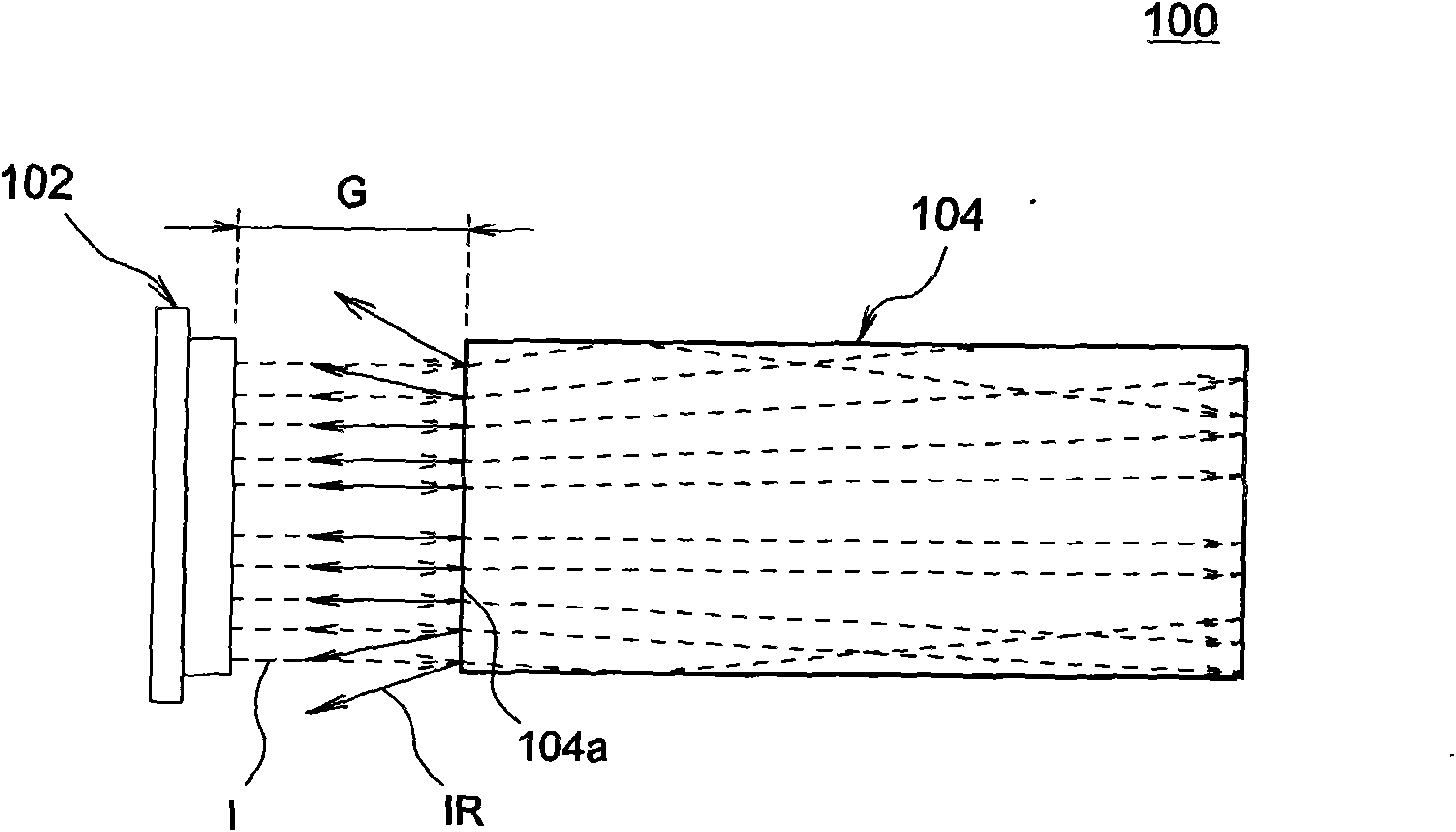
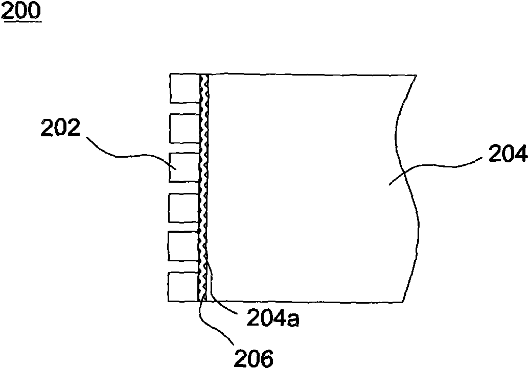
【Technical field】 [0001] The invention relates to a backlight module. 【Background technique】 [0002] figure 1 It is a schematic diagram of a conventional backlight module. Such as figure 1 As shown, in the backlight module 100 , the LED strip 102 is separated from the light incident surface 104 a of the light guide plate 104 by an air layer G. Such as figure 1 As shown by the dotted line path of , a light beam I emitted by the LED light bar 102 first passes through the air layer G to generate the first refraction, and then passes through the light incident surface 104a of the light guide plate 104 after the second refraction, and then passes through the light guide plate 104 The interior travels to provide a large-area luminous effect. However, when the light beam I passes through the light incident surface 104a of the light guide plate 104 from the air layer G, part of the light beam IR (such as figure 1 (shown by the solid line) will be reflected by the light incide...

Claims


Application Information

Patent Timeline
IPC IPC(8): F21S8/00F21V13/00F21V17/00F21Y101/02
Inventor 松本伸吾黄炳锋王川祥杨宏钧
Owner CORETRONIC
Learn More