
Test element for analyzing body fluid

A technology for testing components, body fluids, applied in the field of systems, which can solve problems such as difficult for patients to perform, time-consuming and uncomfortable handling steps

Inactive Publication Date: 2014-09-24
F HOFFMANN LA ROCHE & CO AG
View PDF11 Cites 0 Cited by
  • Summary
  • Abstract
  • Description
  • Claims
  • Application Information

AI Technical Summary

Problems solved by technology

These processing steps are not only time-consuming and uncomfortable, but also difficult to perform for many often elderly and / or affected patients

Method used


Image

  • Test element for analyzing body fluid
  • Test element for analyzing body fluid
  • Test element for analyzing body fluid

Examples


Embodiment Construction

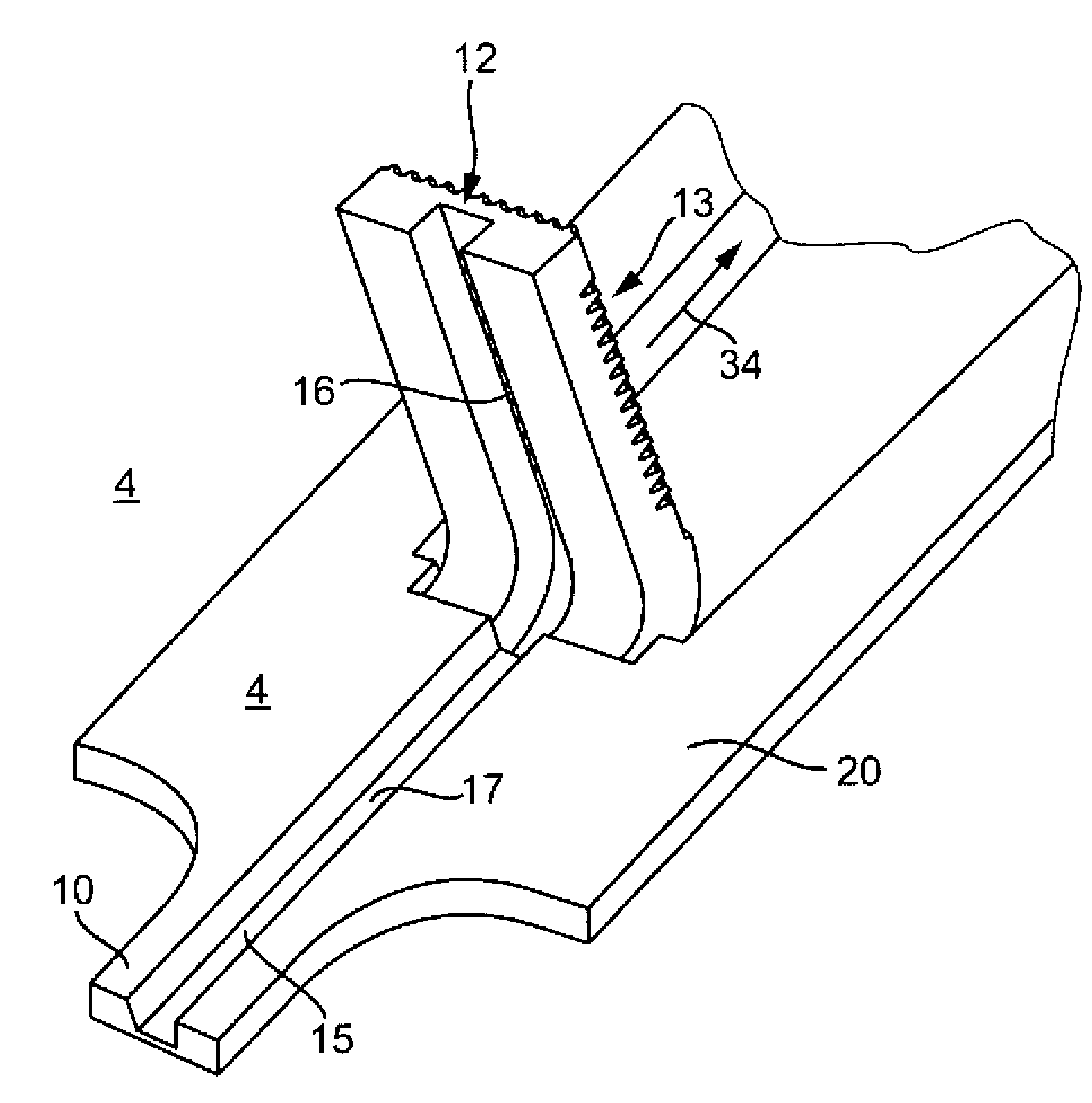
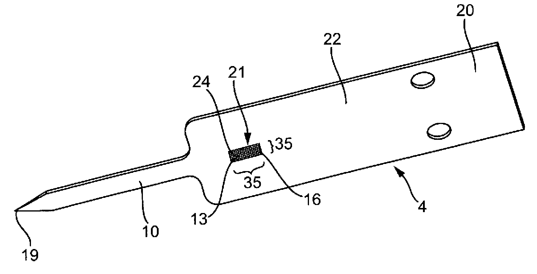
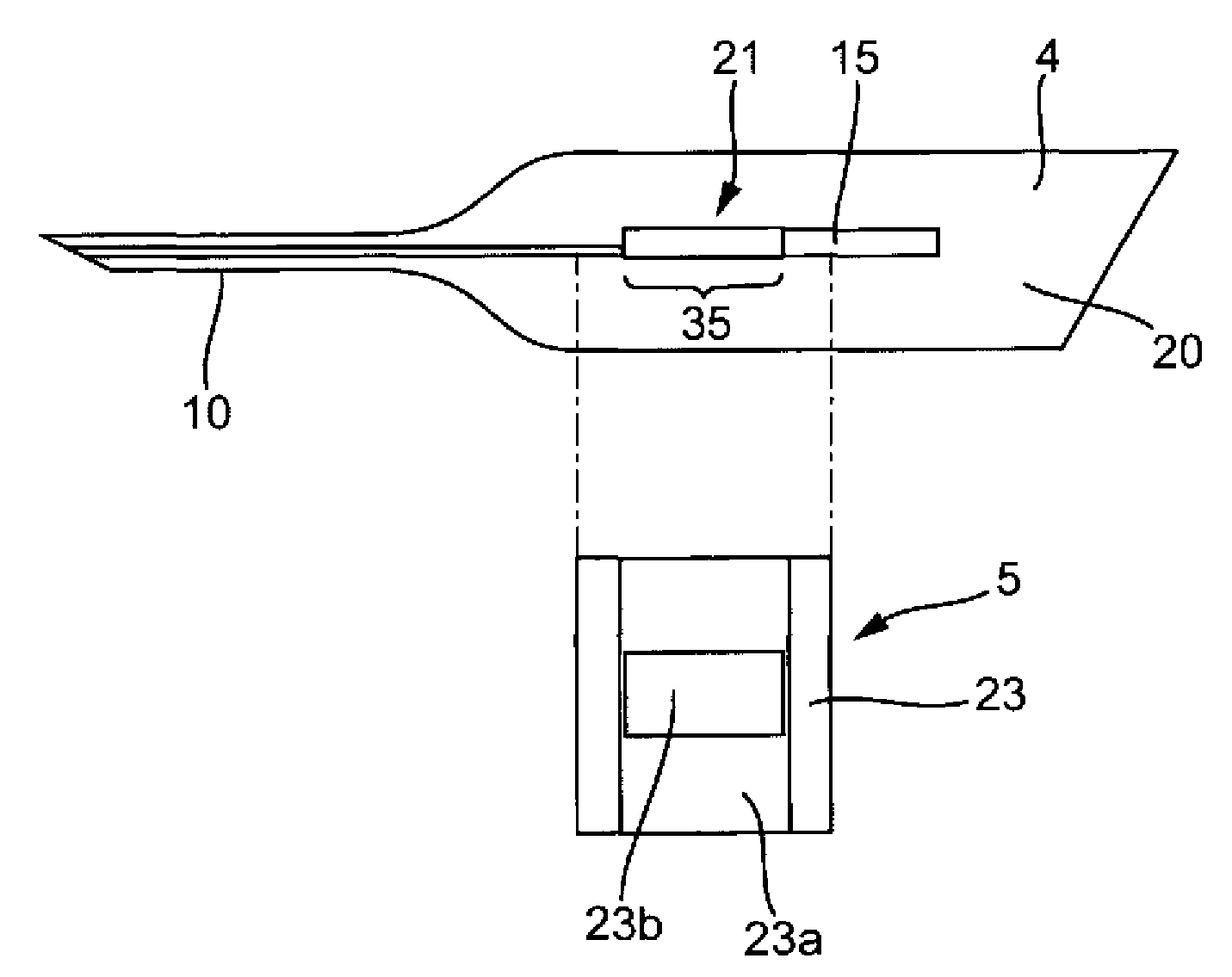
[0071] figure 1 An analysis system 1 is shown, which has an analysis device 2 and a magazine 2 a contained in the device 2 , which has a test element 3 . The test elements 3 each comprise a piercing element 4 and a test panel 5 .

[0072] The evaluation device 2 has a housing 6 and a coupling mechanism 7 for coupling to the piercing element 4 in order to move the piercing element 4 along a movement path in the piercing direction. The coupling mechanism 7 is coupled to a drive unit 7a which moves a coupling structure 7b which can be coupled to the piercing element 4 .

[0073] The measurement and evaluation unit 8 is used to measure changes in reagents which react with the body fluid of the analysis element 5 in order to analyze the body fluid for an analyte. Ability to perform quantitative and qualitative analysis. Preferably, the glucose content in the blood is studied. In the example shown, the measurement and evaluation unit 8 operates according to the photometric princ...


PUM

PropertyMeasurementUnit
thicknessaaaaaaaaaa
thicknessaaaaaaaaaa
sizeaaaaaaaaaa

Abstract

The test element for making a puncture wound in a body part, for receiving a body fluid sample from the body part and for analyzing using a reagent system, whose reaction guides with analytes contained in the body fluid for a modification of one of the characteristic measured parameters of the test element optically measurable for the desired analytical results, comprises a lancing element (3) and a testing field (5), which contains a part of the reagent system. The lancing element has a nib at one end of the lancing element for making the wound in the body part, and a capillary structure. The test element for making a puncture wound in a body part, for receiving a body fluid sample from the body part and for analyzing using a reagent system, whose reaction guides with analytes contained in the body fluid for a modification of one of the characteristic measured parameters of the test element optically measurable for the desired analytical results, comprises a lancing element (3) and a testing field (5), which contains a part of the reagent system. The lancing element has a nib at one end of the lancing element for making the wound in the body part, and a capillary structure that is designed, so that the body fluid penetrates into the capillary structure after inserting the nib of the lancing element into the skin. The lancing element and the testing field are positionable relative to each other in a liquid transfer position, so that the testing field fluidically contacts to a part of the capillary structure of the lancing element. The body fluid penetrating into the capillary structure is transferred to the testing field. The testing field comprises a transparent supporting layer (100) and a testing layer introduced on the supporting layer by coating, where the side of the testing layer turned away from the supporting layer forms the fluid entry side, which is turned towards the capillary structure in the liquid transfer position and directly adjoins to the capillary structure in the liquid transfer position. The testing field is fixed onto the lancing element, so that the lancing element and the testing field are fluidically contacted in a permanent manner. The testing layer includes two partial layers, where a first partial layer coated on the supporting layer is a reaction layer (102) and a second partial layer coated on the supporting layer is an opaque blocking layer (103). The reaction layer and the opaque blocking layer contain an enzyme and a color formation reagent (indicator). The quantity of the enzyme in the reaction layer is higher than in the blocking layer and the quantity of the indicator in the reaction layer is less than in the blocking layer. A component of the reagent system such as enzyme is bound to the supporting layer of the testing field. The capillary structure includes a two-dimensional matrix structure with 100 cells having cell cavities, and a capillary channel, through which the body fluid is transferred to the matrix structure after inserting the nib of the lancing element into the skin. The largest dimension of the cell cavity of the matrix structure is less than the average width of the capillary channels. The cell cavities vertical to the extension of the matrix structure have a defined height, by which the least value of the layer thickness of the fluid layer is enabled. The cells are opened at a transfer side of the matrix structure adjoined to the fluid entry side. The matrix structure is arranged parallel and adjacent to a partial length of the capillary channel. The cells of the matrix structure have cell openings at the fluid entry side opposite to the transfer side turned towards the capillary channel, so that the fluid penetrates through the cell openings in the cell cavity of the matrix structure. The thickness of the testing layer is 20 mu m. The cell cavity of the matrix structure consistently broadens towards the transfer side. The capillary channel and the matrix structure are produced in a common production process step by etching or etching and laser cutting. Independent claims are included for: (1) an analysis system for analyzing a body fluid from a body part; and (2) a method for producing a lancing element with a capillary channel for making a puncture wound in a body part.

Description

technical field [0001] The invention relates to a test element for producing a puncture wound in a body part, for receiving a body fluid from said body part, and for analyzing the body fluid with respect to an analyte contained in the body fluid. A method for producing the test element as well as an analysis system comprising the test element according to the invention and a specially adapted evaluation device capable of evaluating the test element are also objects of the invention. [0002] Such test elements and analysis systems are mainly used for medical analysis. They are common in many variables for quantitative and qualitative determination of different analytes. Systems for determining the glucose concentration in the blood of diabetic patients are of particular medical and economic importance. The present invention is particularly suitable for such systems. However, the present invention is not limited thereto. For example, another important analyte is cholesterol...

Claims


Application Information

Patent Timeline
Patent Type & Authority Patents(China)
IPC IPC(8): A61B5/151G01N33/52C12Q1/54A61B5/00
CPCA61B2562/0295A61B5/14532
Inventor H-P.哈尔J.赫内斯
Owner F HOFFMANN LA ROCHE & CO AG
Learn More