Hammering tool

A technology of impact tools and installation tools, which is applied in the field of impact tools, can solve problems such as poor workability and damage, and achieve the effects of improving reliability, maintaining miniaturization, and excellent operability

Inactive Publication Date: 2012-05-23
MAKITA CORP
View PDF8 Cites 0 Cited by
  • Summary
  • Abstract
  • Description
  • Claims
  • Application Information

AI Technical Summary

Problems solved by technology

Therefore, preparation and replacement of tools are required, resulting in poor workability
If a drill bit can be attached to the impact screwdriver, it can be drilled, but if it is a relatively brittle workpiece such as a tile, it is likely to be damaged due to the impact

Method used


Image

  • Hammering tool
  • Hammering tool
  • Hammering tool

Examples


Embodiment Construction

[0044] Embodiments of the present invention will be described below based on the drawings. In addition, in the form after form 2, the same code|symbol is attached|subjected to the structural part common to form 1, and the overlapping description is abbreviate|omitted.

[0045] [Method 1]

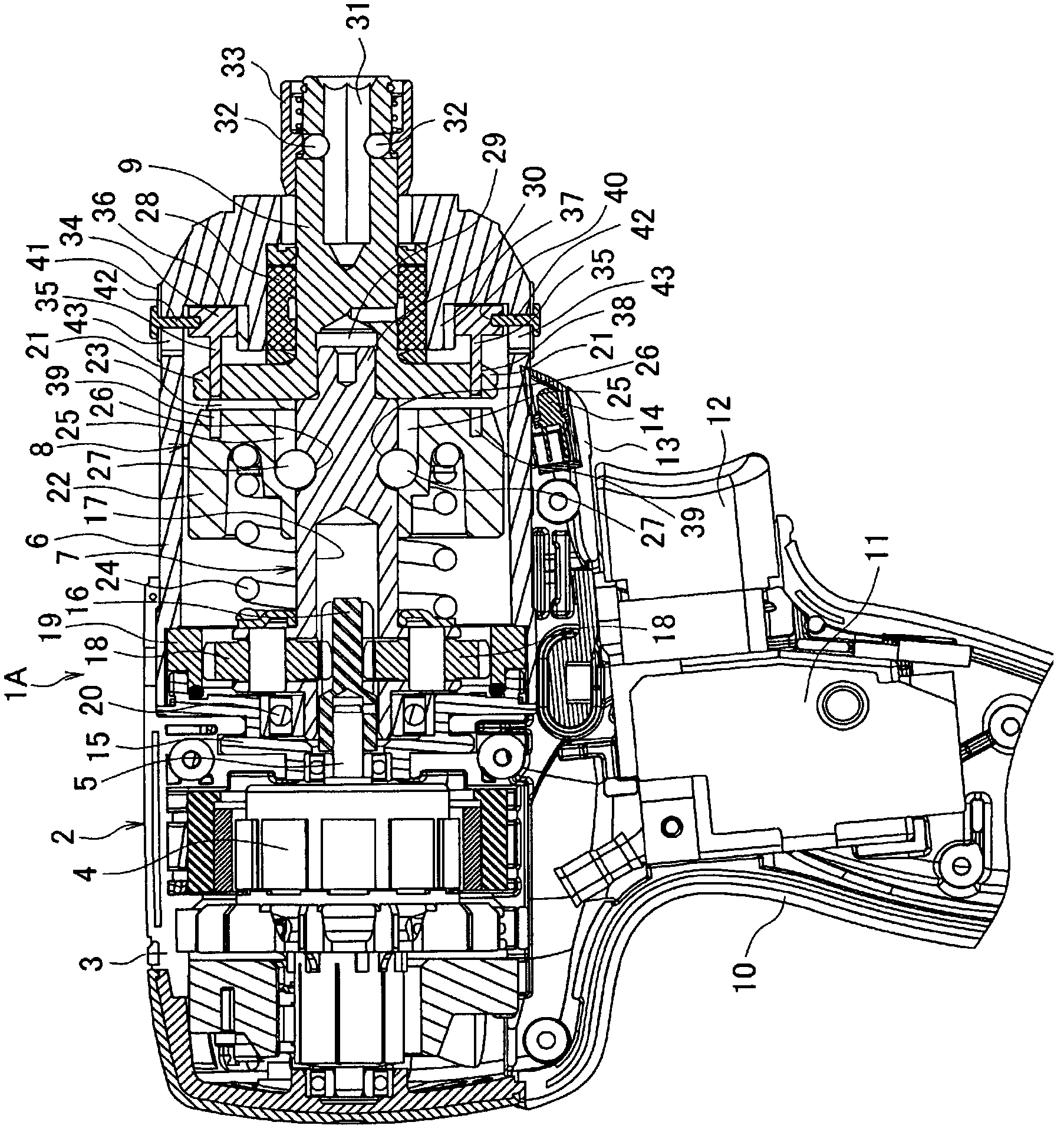
[0046] Such as figure 1 As shown, an impact screwdriver 1A as an example of an impact tool has: a main body case 2, which is formed by assembling left and right half cases 3, 3, and houses a motor 4; and a hammer case 6 with a bell-shaped cross section. , which is the front shell, assembled in front of the main body shell 2 ( figure 1 The right side in the middle), and accommodate the main shaft 7, the impact mechanism 8, and the anvil 9. A handle 10 is extended below the main body case 2 , and a switch 11 with a trigger 12 is housed in the upper portion of the handle 10 . A battery pack (not shown) serving as a power source is installed at the lower end of the handle 10 . Further, in th...


PUM


Abstract

Disclosed is a method for obtaining a drilling mode with high reliability. As an embodiment of the above, there is disclosed an arrangement wherein a joint ring (34) that rotates integrally with an anvil (9) in a hammer case (6), in such a way that connecting pins (35) protruding rearward are inserted forward through an arm (21), is provided in such a manner as to be capable of moving back and forth between an advanced position where the connecting pins (35) pass only through the arm (21) and a retreat position where the connecting pins (35) pass through the arm (21) and are inserted into blind holes (39) formed in the front surface of a hammer (22), wherein meanwhile an operating ring (41) that is capable of subjecting the joint ring (34) to sliding operation between the advanced position and the retreat position is provided in the hammer case (6), and wherein when the joint ring (34); is moved by the operating ring (41) to the retreat position, then the hammer (22) and the arm (21) are integrated together in the rotational direction via the joint ring (34), thereby preventing the hammer (22) from coming off, thus causing the anvil (9) and a spindle (7) to rotate integrally together.

Description

technical field [0001] The present invention relates to an impact tool such as an impact driver that generates rotational impact force on an anvil protruding forward of a casing. Background technique [0002] In an impact tool such as an impact screwdriver, there are: a main shaft that is rotated by a motor in a housing; A pair of claws protrude from the front surface of the hammer; the anvil is supported by the housing coaxially with the main shaft, the front end of the installation tool head protrudes to the front of the housing, and a pair of radial arms are formed at the rear end; the coil spring, The hammer is biased toward an advanced position where the claw and the arm engage in the rotational direction. That is, when the torque of the anvil is large, the hammer moves back and separates from the arm guided by the ball rolling in the groove, and then advances while rotating by the biasing force of the coil spring to engage with the arm, and repeats this process. This...

Claims


Application Information

Patent Timeline
Patent Type & Authority Applications(China)
IPC IPC(8): B25B21/02
CPCB25B21/00B25B21/026
Inventor 平林德夫近藤友幸长坂英纪木村和也
Owner MAKITA CORP
Why Eureka
Try Eureka