Turbo engine having steam tapping

A technology for turbines and inner shells, which is applied to gas turbine devices, mechanical equipment, engine components, etc., and can solve the problems of axial positioning restrictions of exhaust ports, heat consumption and power reduction, etc.

Inactive Publication Date: 2012-05-23
SIEMENS AG
View PDF6 Cites 4 Cited by
  • Summary
  • Abstract
  • Description
  • Claims
  • Application Information

AI Technical Summary

Problems solved by technology

However, the axial positioning of the exhaust openings is thus strongly restricted and can lead to increased heat consumption and reduced power

Method used


Image

  • Turbo engine having steam tapping
  • Turbo engine having steam tapping
  • Turbo engine having steam tapping

Examples


Embodiment Construction

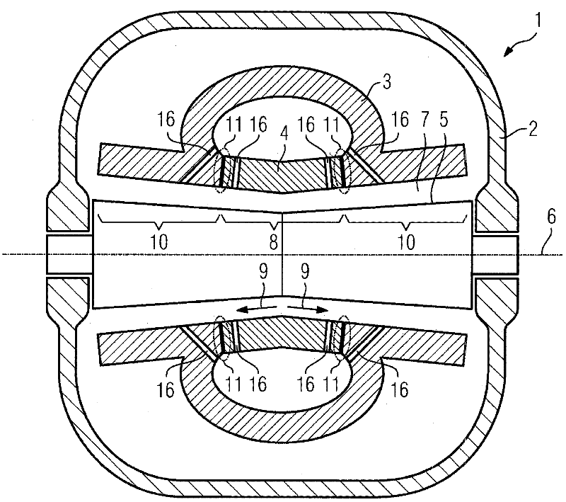
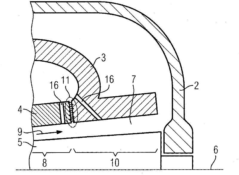
[0020] figure 1 The steam turbine 1 shown as an embodiment of a turbomachine basically comprises an outer housing 2 , an outer inner housing 3 arranged in the outer housing 2 and an inner inner housing 4 arranged in the outer inner housing 3 .

[0021] In the outer inner housing 3 and the inner inner housing 4 , a rotor 5 is mounted rotatably about an axis of rotation 6 . Flow channels 7 are formed between the outer inner housing 3 and the rotor 5 and between the inner inner housing 4 and the rotor 5 . For the sake of clarity, the individual rotor blades and guide blades are not shown in detail. The guide vanes are arranged on the inner inner housing 4 and on the outer inner housing 3 . On the rotor 5 the moving blades are arranged such that in the flow channel 7 the thermal energy of the steam can be converted into rotational kinetic energy. First, steam flows through a steam inlet region (not shown in detail) into the first flow region 8 which is arranged between the inn...


PUM


Abstract

The invention relates to a three-shelled steam turbine (1), wherein a rotor (5) is rotatably supported and an internal inner housing (4) and an external inner housing (3) are disposed about the rotor (5), wherein the joint (11) between the internal inner housing (4) and the external inner housing (3) is sealed and tapping holes (16) are disposed in the internal inner housing (4) and / or the external inner housing (3).

Description

technical field [0001] The invention relates to a turbomachine comprising a rotor mounted rotatably about an axis of rotation, an inner inner casing and an outer inner casing arranged around the rotor, and an outer casing arranged around the inner inner casing and the outer inner casing body, wherein the outer inner housing is arranged around the inner inner housing along the region of the axis of rotation, wherein a flow region for the flow of the flow medium is formed between the rotor and the inner inner housing and the outer inner housing . Background technique [0002] A turbine can be understood to mean, for example, a steam turbine. Steam turbines generally have a rotatably mounted rotor and an inner housing arranged around the rotor. A flow channel is formed between the rotor and the inner housing. The casing of a steam turbine must be able to fulfill several functions. On the one hand, the guide vanes are arranged in the flow channels on the housing, and on the ...

Claims


Application Information

Patent Timeline
IPC IPC(8): F01D9/04F02C7/28F01D17/10
CPCF01D25/24F01D11/005F05B2240/57F01D9/041F01D17/105F01D9/04F05D2240/55F01D3/02
Inventor 马丁·库恩克里斯托夫·克斯特纳鲁道夫·波特
Owner SIEMENS AG
Why Eureka
Try Eureka