Bulb-shaped lamp
A technology of electric light bulbs and shaped lamps, which is applied in the direction of lampshades, electric light sources, circuit layout, etc., which can solve the problems of insufficient irradiation and achieve the effect of suppressing high temperature
- Summary
- Abstract
- Description
- Claims
- Application Information
AI Technical Summary
Problems solved by technology
Method used
Image
Examples
no. 1 approach
[0050]
[0051] figure 1 It is a cross-sectional view of a lighting fixture for an ordinary incandescent light bulb equipped with the light bulb-shaped LED lamp 1 of the first embodiment. This lighting fixture 70 has a hemispherical (bowl-shaped) fixture main body 71 attached to the ceiling, and a lamp socket 72 attached to the fixture main body 71 . The lamp socket 72 is in a state where the insertion port for inserting the cap for the ordinary incandescent light bulb is opposed to the opening 71a formed on the peripheral surface of the device main body 71, and is slightly inclined with respect to the horizontal line so that the insertion port side is located on the lower side. In the state, it is supported by the outside of the main body part 71 of the appliance.
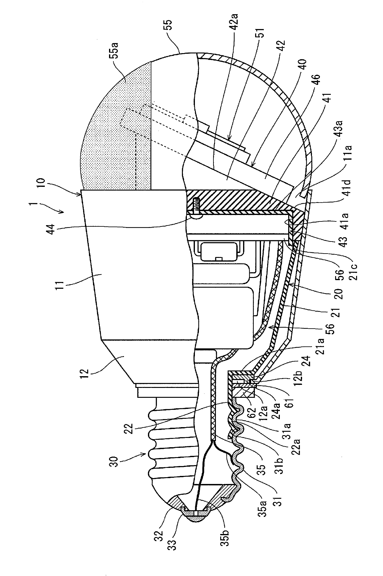
[0052] figure 2 It is a partly broken side view which shows the schematic structure of the light bulb-shaped LED lamp 1 of this embodiment, image 3 It is an exploded perspective view showing main parts of t...
no. 2 approach
[0170] Figure 10 It is a cross-sectional view of a lighting fixture for an ordinary incandescent light bulb equipped with the light bulb-shaped LED lamp 100 of the second embodiment. exist Figure 10 The luminaire 70 shown in the figure 1 Similarly, the lighting fixture 70 shown in FIG. 2 has a hemispherical (bowl-shaped) fixture main body 71 mounted on the ceiling, and a lamp socket 72 mounted on the fixture main body 71 . The lamp socket 72 is in a state where the insertion port for inserting the cap for the ordinary incandescent light bulb is opposed to the opening 71a formed on the peripheral surface of the device main body 71, and is slightly inclined with respect to the horizontal line so that the insertion port side is located on the lower side. In the state, it is supported by the outside of the main body part 71 of the appliance.
[0171] Figure 11 It is a sectional view showing the schematic structure of the light bulb-shaped LED lamp 100 of this embodiment.
...
no. 3 approach
[0243] Figure 16 It is a longitudinal sectional view of the light bulb-shaped LED lamp 200 in this embodiment, Figure 17 is a perspective view of its exploded representation.
[0244] The light bulb-shaped LED lamp 200 of this embodiment includes: figure 1The lamp cap 230 of the lamp cap 230 of the same lamp cap 70 shown in FIG. The LED module 250 and the translucent outer cylinder 220 attached to the base 210 cover the LED module 250 .
[0245] The base 230 has a cylindrical casing 231 , and a lighting circuit unit 260 for lighting the LED module 250 is provided inside the casing 231 . Therefore, in the light bulb-shaped LED lamp of this embodiment, the circuit unit case, circuit case, etc. provided in the light bulb-shaped LED lamp of each embodiment mentioned above are not provided.
[0246] The base 210 has a cylindrical base main body 213 , a base bottom 215 covering one end surface of the base main body 213 except for the center, and a base 230 from around the cent...
PUM
 Abstract
Description
Claims
Application Information
 - R&D
- Intellectual Property
- Life Sciences
- Materials
- Tech Scout
- Unparalleled Data Quality
- Higher Quality Content
- 60% Fewer Hallucinations
Browse by: Latest US Patents, China's latest patents, Technical Efficacy Thesaurus, Application Domain, Technology Topic, Popular Technical Reports.
© 2025 PatSnap. All rights reserved.Legal|Privacy policy|Modern Slavery Act Transparency Statement|Sitemap|About US| Contact US: help@patsnap.com


