
Light assembly

A technology of lamp components and lighting components, which can be applied to vehicle parts, parts of lighting devices, semiconductor devices of light-emitting elements, etc., and can solve problems such as limitations

Inactive Publication Date: 2012-05-23
3M INNOVATIVE PROPERTIES CO
View PDF18 Cites 8 Cited by
  • Summary
  • Abstract
  • Description
  • Claims
  • Application Information

AI Technical Summary

Problems solved by technology

Automotive lights seem to overcome this shortcoming by having a curved outer surface, but they are still limited in that light is still extremely directional no matter how curved it is.

Method used


Image

  • Light assembly
  • Light assembly
  • Light assembly

Examples


Embodiment Construction

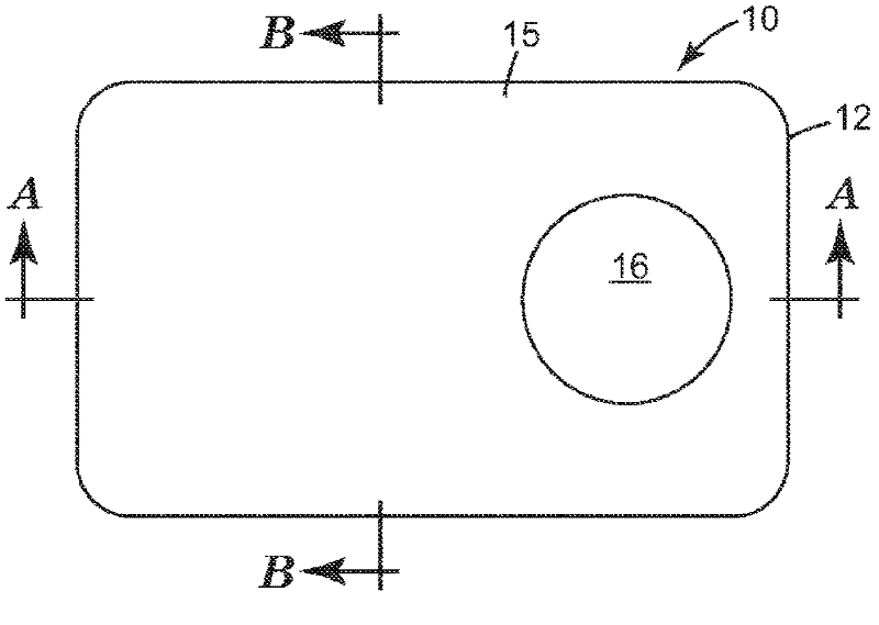
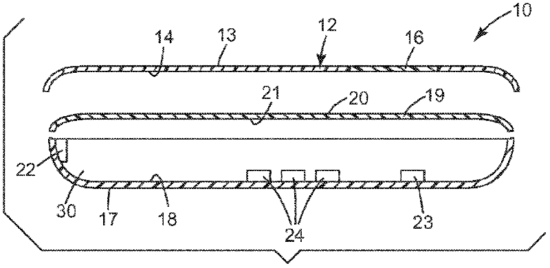
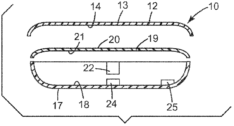
[0027] refer to figure 1 , Figure 1A with Figure 1B, shows an exemplary lamp assembly of the present invention. The automotive tail light assembly 10 has an (optionally curved) outer light housing 12 having substantially opposite first and second major surfaces 13 and 14, a first region 15 having a first color, such as red and a second region 16 of a second different color, such as clear or white. The automobile taillight assembly 10 also includes: a reflector 17 having an inner major surface 18; an inner lens 19 disposed between the outer lamp housing 12 and the reflector 17, wherein the inner lens 19 has substantially opposite first and second major surfaces 20, 21, and wherein at least one of the first or second major surfaces 20, 21 is transflective; and a first light source 22 emitting a first color (eg red) when energized. There is an optical cavity 30 between the inner lens major surface 21 and the reflector major surface 18 . The first light source 22 (e.g. red...


PUM


Abstract

The invention discloses a light assembly having reflector (17), a light source (22), an outer light cover (12) having a first color zone (15) and a second, different color or clear zone (16), and an inner lens (19) with a transflective surface. Embodiments of light assemblies described herein are useful, for example, as signs, backlights, displays, task lighting, luminaire, and vehicle (e.g., cars, trucks, airplanes, etc.) components. Vehicle comprising light assemblies include those where the light assembly is a vehicle tail light assembly.

Description

Background technique [0001] Light source applications are well known in the art and include those configured to emit light relatively uniformly over a given area in a given desired direction. The degree of uniformity and aiming is application specific, but the emission area is usually comparable to the device being illuminated. [0002] Common lighting applications include backlighting for displays and signs, as well as automotive lights. Liquid crystal displays (LCDs) are commonly used in laptop computers, monitors and televisions. Since the liquid crystal itself does not generate light, but only modulates it, it is common practice to provide illumination behind the LCD, called a backlight. This backlight is approximately the same size as the LCD and provides a beam of light directed through the LCD toward the viewer. One type of backlight often includes at least one fluorescent lamp illuminating the edges of the plastic light guide. Light is extracted from the light guid...

Claims


Application Information

Patent Timeline
Patent Type & Authority Applications(China)
IPC IPC(8): F21S8/10F21V9/08F21Y101/02
CPCF21S48/2218B60Q1/2696B60Q1/2607F21Y2101/02F21S48/215F21V13/08F21Y2115/10F21S43/14F21S43/255F21W2103/10F21W2103/35F21W2103/45F21W2103/20F21W2103/00
Inventor 蒂莫西·V·斯塔格戴维·A·安德马克·E·纳皮耶腊拉巴里·S·卡朋特
Owner 3M INNOVATIVE PROPERTIES CO
Learn More