Mixer monitoring

A mixer, high-frequency signal technology, applied in the direction of reflection/re-radiation, utilization and re-radiation of instruments, radio waves, etc., to achieve the effect of allowing control and monitoring, simple control and monitoring

Inactive Publication Date: 2012-05-23
ROBERT BOSCH GMBH
View PDF3 Cites 0 Cited by
  • Summary
  • Abstract
  • Description
  • Claims
  • Application Information

AI Technical Summary

Problems solved by technology

Nevertheless, in the prior art, either no mixer monitoring is used or only a simple and insensitive mixer monitoring

Method used


Image

  • Mixer monitoring
  • Mixer monitoring
  • Mixer monitoring

Examples


Embodiment Construction

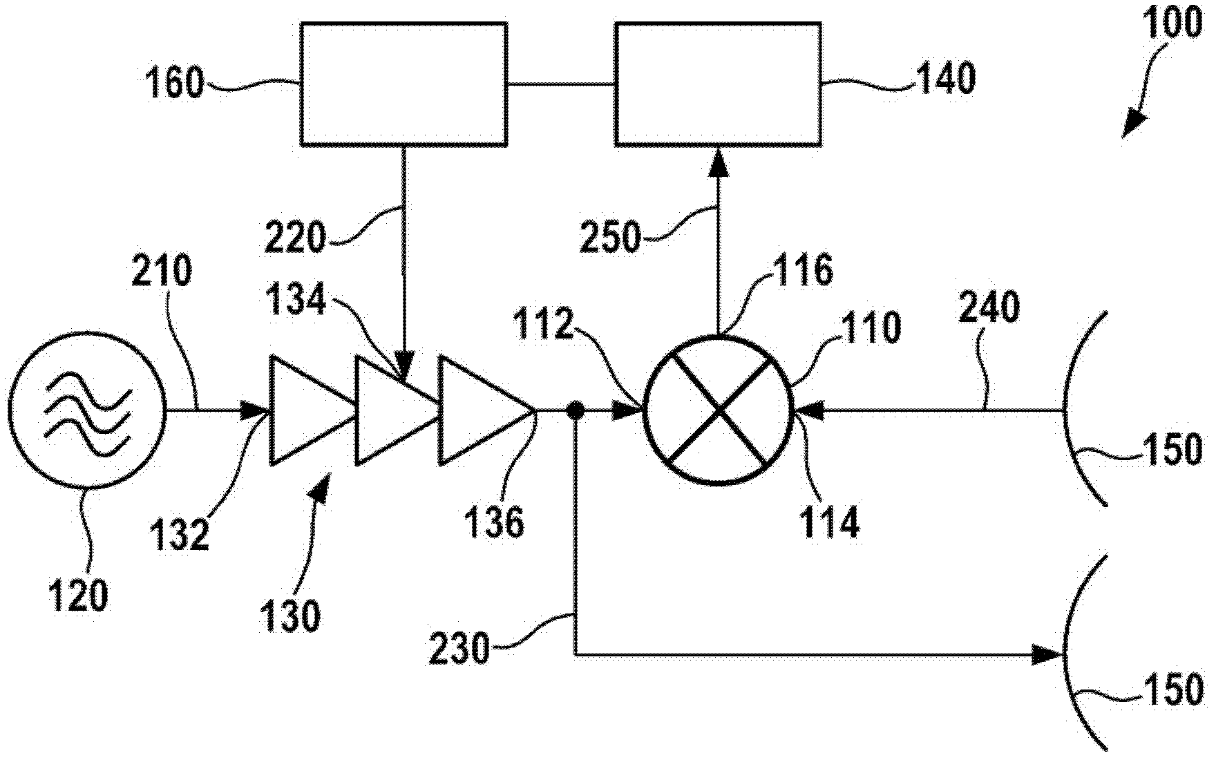
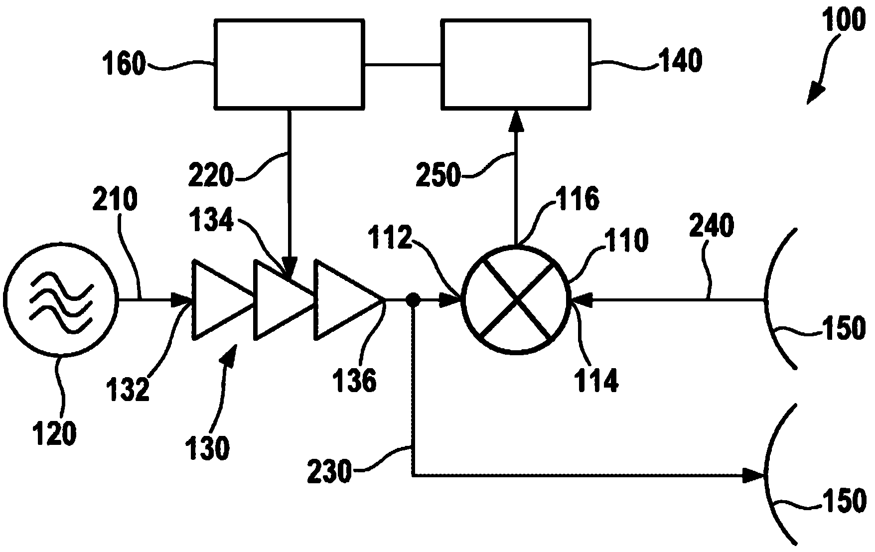
[0018] figure 1 A schematic diagram of a radar system 100 is shown. Radar system 100 may be, for example, a frequency-modulated continuous wave radar. Radar system 100 can be used, for example, for adaptive driving speed regulation in a motor vehicle.

[0019] Radar system 100 has a voltage-controlled oscillator 120 . The voltage controlled oscillator is used to generate a high frequency signal 210 . The high-frequency signal 210 may, for example, have a frequency in the order of 77 GHz. Preferably, the voltage controlled oscillator allows adjustment of the frequency of the high frequency signal 210 . Instead of the voltage-controlled oscillator 120 , another component for generating the high-frequency signal 210 may also be provided.

[0020] Furthermore, radar system 100 also includes an amplifier 130 with an adjustable amplification factor. Amplifier 130 has an amplifier input 132 , a modulation input 134 and an amplifier output 136 . Amplifier input 132 is connected...


PUM


Abstract

A method for checking the operability of a mixer (110) involves the mixer (110) being supplied with a radio-frequency signal (230) and a radio-frequency comparison signal (240) in order to produce a baseband signal (250). In this case, the amplitude of the radio-frequency signal (230) is altered on the basis of time. A DC voltage component of the baseband signal (250) which is output by the mixer (110) is evaluated in order to assess the operability of the mixer (110).

Description

technical field [0001] The invention relates to a method for checking the functionality of a mixer according to claim 1 and to an electronic circuit arrangement according to claim 9 . Background technique [0002] In radar systems, microwave mixers are used to mix the high-frequency transmitted signal with the received reflected signal, and in this way obtain a baseband signal with a lower frequency, which nevertheless has the same information content. In systems where safety is important, mixer functionality needs to be monitored. Nevertheless, in the prior art either no mixer monitoring or only simple and insensitive mixer monitoring is used. Contents of the invention [0003] The object of the present invention is to specify a method for checking the functionality of a mixer. The object is solved by a method with the features of claim 1 . It is also the object of the invention to provide an electronic circuit arrangement for checking the functionality of a mixer. T...

Claims


Application Information

Patent Timeline
Patent Type & Authority Applications(China)
IPC IPC(8): G01S7/40G01S13/34
CPCG01S7/4021H03D2200/0045G01S13/34G01S7/35G01S7/4056G01S7/406G01S7/4069
Inventor A·希默尔施托斯M·沙博
Owner ROBERT BOSCH GMBH
Why Eureka
Try Eureka