Overmoulded safety and waterproof photo voltaic connector

A technology of connectors and female connectors, which is applied in the direction of connection, parts of connection devices, assembly/disassembly of contacts, etc., and can solve the problems that connectors cannot be completely impervious to water and have low efficiency

Inactive Publication Date: 2012-05-23
ASAHI BEST BASE
View PDF10 Cites 3 Cited by
  • Summary
  • Abstract
  • Description
  • Claims
  • Application Information

AI Technical Summary

Problems solved by technology

Therefore, this connector is still not completely watertight
In addition, the manufacturing process of the outer ...

Method used


Image

  • Overmoulded safety and waterproof photo voltaic connector
  • Overmoulded safety and waterproof photo voltaic connector
  • Overmoulded safety and waterproof photo voltaic connector

Examples


Embodiment Construction

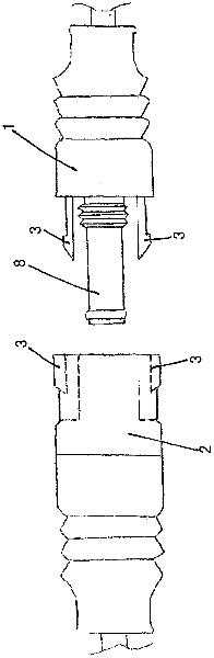
[0028] refer to figure 2 , a preferred schematic embodiment of a PV connector according to the invention is shown prior to assembly with a male connector 1 aligned on one side and a female connector 2 aligned on the other side, however Figure 1 shows State-of-the-art PV connectors.

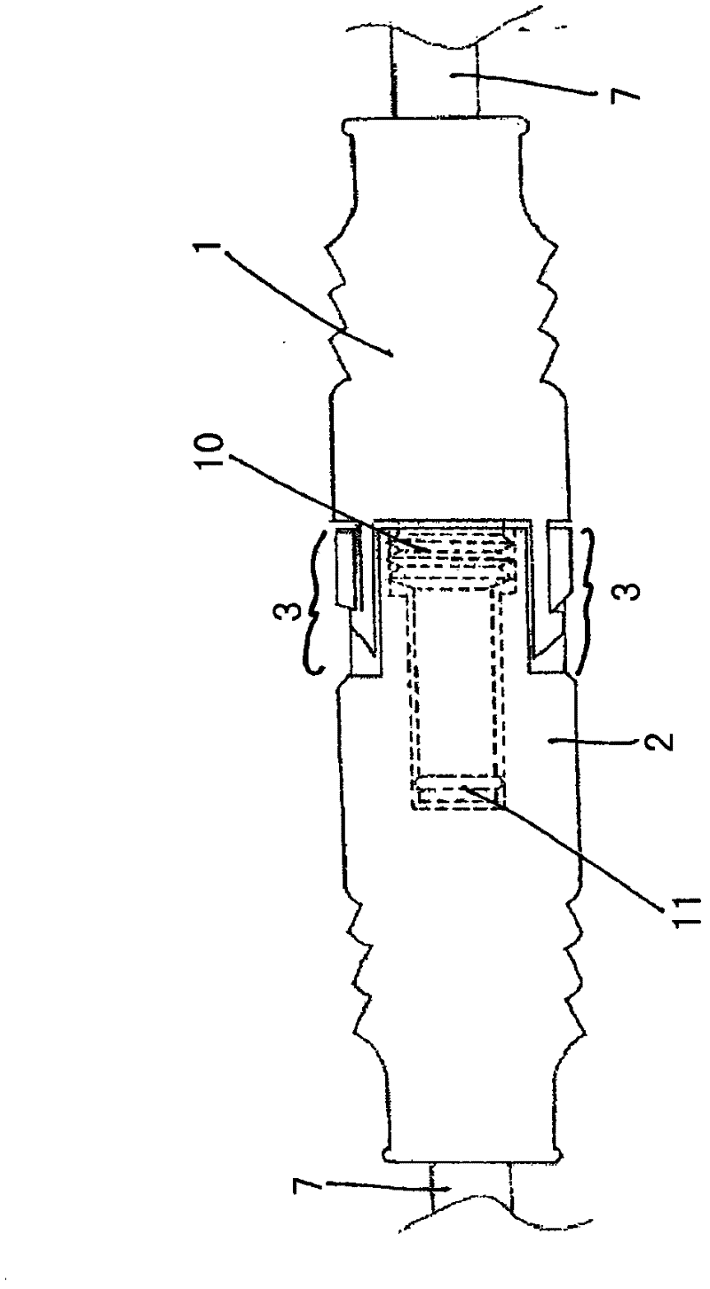
[0029] Both the male connector 1 and the female connector 2 of the present invention are made of insulating resin, preferably polycarbonate, and have a corrugated outer surface to provide better engagement. When the male connector 1 and the female connector 2 as image 3 When assembled together as shown for use as the PV connector of the present invention, the male connector 1 and the female connector 2 are attached by a locking device having locking pieces 3 on both sides for engaging each other. Synthetic locking structure.

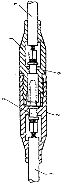
[0030] The female connector 2 is a receptacle shell with a tubular socket 4. The interior of the tubular socket 4 surrounds a tubular male terminal 5 made of PH bronze p...


PUM


Abstract

The male connector of a PV connector has an inner portion of a tubular plug (8) encasing a tubular female terminal (9) that is crimped to a PV cable (7) at its proximal end (6), wherein the tubular plug (8) has a waterproof valve (10) and waterproof ring (11) attached to it in such a way that they are adapted to provide a tight waterproof seal when the tubular plug (8) is fully engaged with a corresponding tubular receptacle (4) of the female connector (2) upon assembly and coupling together, and together with completely overmoulding the male and female connectors (1) (2) with insulating resin, to fully protect and waterproof the crimped connections (6) of the terminals (5) (9) and the PV cables (7) within.

Description

technical field [0001] The present invention relates to the field of electronic plug-in connectors, in particular to connectors for photovoltaic cables for electrical connection of solar panels that are waterproof and safe. Background technique [0002] Photovoltaic cable connectors, usually called photovoltaic connectors or PV connectors, are generally plug-in types including plugs and sockets. The plug socket or male connector has at least one contact sleeve or female terminal, and has at least one contact pin. or male terminal socket housing or female connector coupling, wherein a plug having a female connector is inserted into a socket housing having a male connector in such a way that, at the other end attached to the male connector and the female connector An electrical connection is established between two corresponding cables at the other ends of the cables, and the other ends are respectively fixed to the cables by crimping. [0003] An example of such a connector ...

Claims


Application Information

Patent Timeline
IPC IPC(8): H01R13/52H01R13/639
CPCH01R11/11H01R43/24H01R13/5219H01R13/6273
Inventor 江田昌荣
Owner ASAHI BEST BASE
Why Eureka
Try Eureka