Composite substrate and manufacturing method for the same

一种复合基板、贴合基板的技术,应用在压电/电致伸缩器件的制造/组装、阻抗网络、压电器件/电致伸缩器件等方向,能够解决压电基板的端部裂纹等问题,达到减少不良情况、抑制不良情况的效果

Active Publication Date: 2012-05-23
NGK INSULATORS LTD
View PDF6 Cites 9 Cited by
  • Summary
  • Abstract
  • Description
  • Claims
  • Application Information

AI Technical Summary

Problems solved by technology

At this time, due to the influence of expansion and contraction caused by heating, cracks may occur at the end of the piezoelectric substrate.

Method used


Image

  • Composite substrate and manufacturing method for the same
  • Composite substrate and manufacturing method for the same
  • Composite substrate and manufacturing method for the same

Examples


Embodiment 1

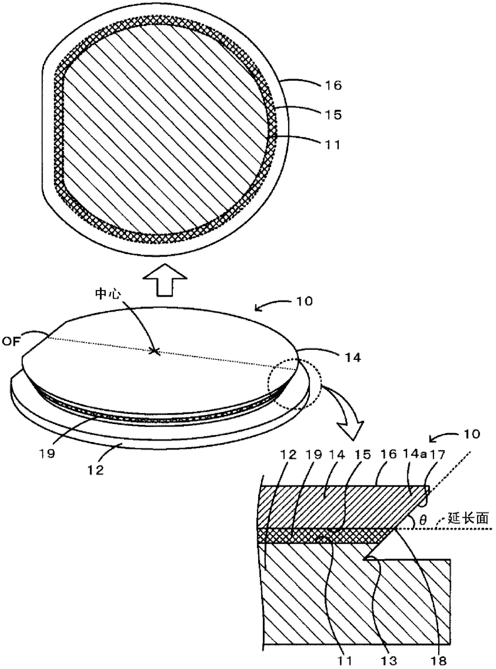
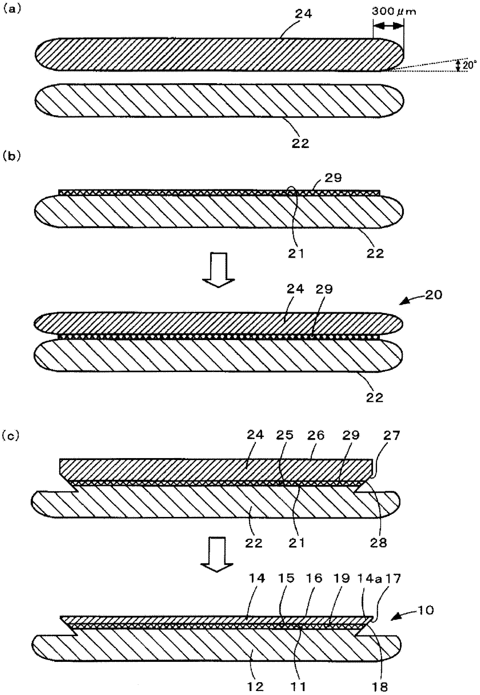
[0058] First, a lithium tantalate substrate (LT substrate) having an orientation flat portion (OF) portion, a diameter of 100 mm, and a thickness of 250 μm was prepared as the piezoelectric substrate 14 . In addition, a silicon substrate having an OF portion, a diameter of 100 mm, and a thickness of 350 μm as a support substrate was prepared as a support substrate 12 ( figure 2 (a)). Here, as the LT substrate, prepare a 42° Y-cut X-transmission LT substrate with the surface acoustic wave (SAW) propagation direction as X and the cut-out angle as a rotation Y cut plate. In addition, the corners of the LT substrate were chamfered. Such as figure 2 As shown in (a), chamfering starts at a position 300 μm inward from the outer peripheral surface of the LT substrate, and the chamfering angle at this position is 20°. Next, utilize the spin-coating method to coat epoxy adhesive on silicon substrate, stick LT substrate and heat to 180 ℃, form the thickness of bonding layer 19 (the ...

Embodiment 2、3

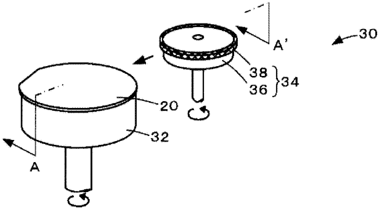
[0062] In addition to grinding the outer peripheral surface of the bonded substrate 20 using the grindstone portion 38 whose angles θ formed by the extended surface of the bonding surface 11 and the tangent line at the intersection portion 18 are 60° and 70°, respectively, the same method as in Example 1 was used. Composite substrates 10 obtained in the same steps are referred to as Examples 2 and 3, respectively.


PUM

PropertyMeasurementUnit
angleaaaaaaaaaa
diameteraaaaaaaaaa
diameteraaaaaaaaaa

Abstract

A composite substrate (10) is a substrate used in an acoustic wave device, and is provided with supporting substrate (12), a piezoelectric substrate (14), and an adhesion layer (19) adhering the supporting substrate (12) and the piezoelectric substrate (14). On the composite substrate (10), assuming a surface of the piezoelectric substrate (14) of a side that is adhering to the supporting substrate (12) to be a first surface (15), and a surface of the opposite side of the first surface to be a second surface (16), the piezoelectric substrate (14) is formed so that if the first surface (15) is projected onto the second surface (16) when the surfaces are arranged vertically, the first surface (15) fits in the inner side of the second surface (16). That is to say, the outer peripheral surface of the piezoelectric substrate (14) is formed so that the outer periphery becomes larger toward the upper surface side. In this manner, on the upper side of an adhering surface (11) of the supporting substrate (12), the piezoelectric substrate (14) is formed to be larger than the adhering surface (11) so that, for example, stress generated by heat on an edge of the composite substrate (10) can be relaxed.

Description

technical field [0001] The invention relates to a composite substrate and a manufacturing method thereof. Background technique [0002] Conventionally, there is known a technique of manufacturing an elastic wave device by providing electrodes on a composite substrate obtained by bonding a support substrate and a piezoelectric substrate. Here, the elastic wave element is used, for example, as a bandpass filter of communication equipment such as a mobile phone. Also, there is known a composite substrate in which lithium niobate or lithium tantalate is used as a piezoelectric substrate, and silicon, quartz, or the like is used as a supporting substrate (see Patent Document 1). [0003] Patent Document 1: Japanese Patent Laid-Open No. 2006-319679 [0004] Such a composite substrate is often produced by preparing a piezoelectric substrate and a support substrate, bonding these substrates with an organic adhesive layer interposed therebetween, and then reducing the thickness of ...

Claims


Application Information

Patent Timeline
Patent Type & Authority Applications(China)
IPC IPC(8): H03H9/25H01L41/09H01L41/18H01L41/22H03H3/08H03H9/145
CPCH03H9/02574H03H3/08Y10T29/42H10N30/073H10N30/086
Inventor 小林弘季堀裕二岩崎康范
Owner NGK INSULATORS LTD
Why Eureka
Try Eureka