
Flywheel mechanism for hammer of light electric piling machine

A technology of pile driver and hammer head, which is applied in the direction of sheet pile wall, foundation structure engineering, construction, etc. It can solve the problems of time-consuming, laborious, and inability to use large-scale piling equipment, etc., and achieves good effect and increased hammering energy.

Inactive Publication Date: 2012-05-30
武荣光
View PDF0 Cites 0 Cited by
  • Summary
  • Abstract
  • Description
  • Claims
  • Application Information

AI Technical Summary

Problems solved by technology

Lake scientific investigations and research experiments often require piling, but due to the limitations of water transportation and the depth of the research area, it is often not possible to use large-scale piling equipment. When there is no light piling machine, manual piling has to be used, which is time-consuming and laborious.

Method used


Image

  • Flywheel mechanism for hammer of light electric piling machine
  • Flywheel mechanism for hammer of light electric piling machine

Examples


Embodiment Construction

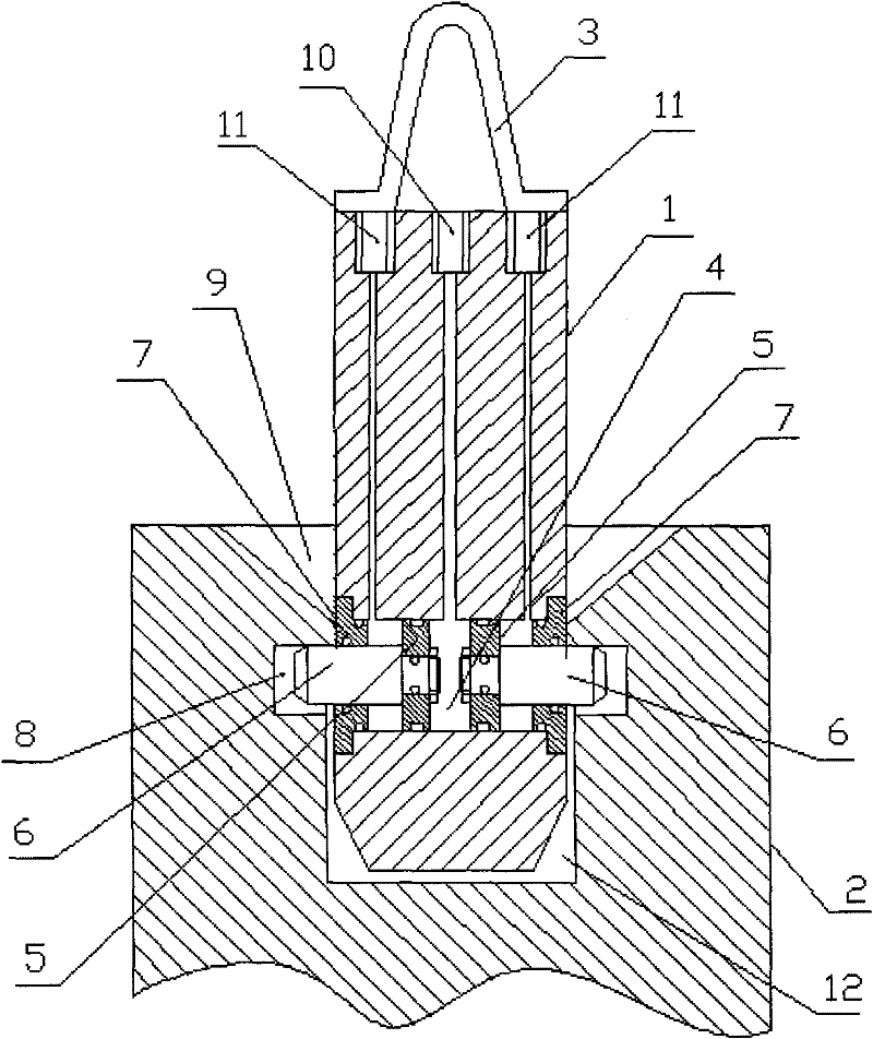
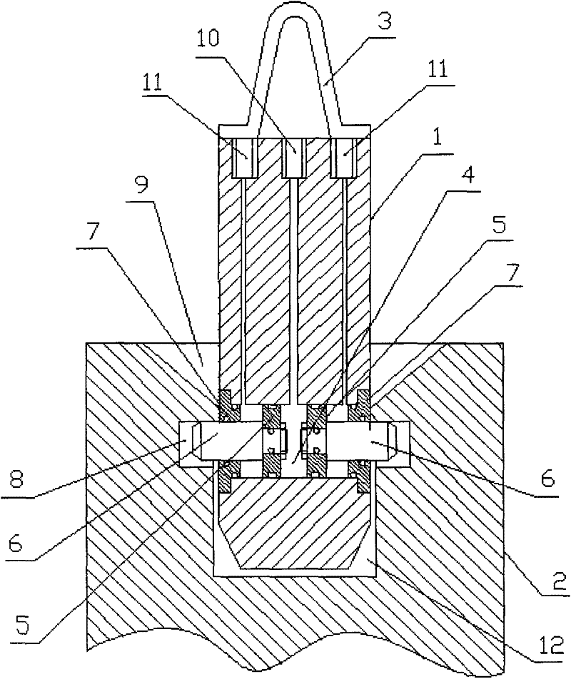
[0008] A blind hole 12 is formed in the middle of the hammer head 2, and the upper mouth of the blind hole 12 is formed with a bell mouth 9, and the middle end of the blind hole 12 is formed with an annular groove 8. The left and right hydraulic cylinders 4 are symmetrically installed in the middle of the hydraulic cylinder 4. Two pistons 6 are installed on each of the two pistons. The cylinder cover 7, the cylinder cover 7 seals the mouth of the hydraulic cylinder 4, and an oil inlet 10 is formed in the center of the hanging hammer 2, and the oil inlet 10 communicates with the middle of the hydraulic cylinder 4, and two holes in the center of the hanging hammer 1 Each side is formed with an oil return hole 11, and the oil return hole 11 communicates with the piston rod cavity on the left and right sides of the hydraulic cylinder 4 respectively, and the lifting ring 3 is installed and fixed on the top of the hanging hammer 1.


PUM


Abstract

The invention discloses a flywheel mechanism for a hammer of a light electric piling machine, which is characterized in that: a blind hole is formed in the middle of the hammer; a horn mouth is formed at the upper opening part of the blind hole; an annular groove is formed at one end of the middle of the blind hole; a hydraulic cylinder which is vertical to an axial line of a drop hammer and is in left-and-right communication with the axial line is arranged on the drop hammer; two pistons are symmetrically installed in the middle of the hydraulic cylinder; each of the two pistons is respectively provided with a same piston rod; each of opening parts at two sides of the hydraulic cylinder is respectively provided with a cylinder cover; each opening part of the hydraulic cylinder is sealed by each cylinder cover; an oil supply hole is formed at the central part of the drop hammer; the oil supply hole is communicated with the middle of the hydraulic cylinder; an oil return hole is respectively formed at each of two sides of the center of the drop hammer; the oil return holes are respectively communicated with piston rod cavities at the left and right sides of the hydraulic cylinder; and a suspension ring is fixedly installed at the top of the drop hammer 1.

Description

technical field [0001] The invention relates to a light electric pile driver, in particular to a hammer head flywheel mechanism of the light electric pile driver, which belongs to the technical field of pile driving machinery. Background technique [0002] Pile drivers are one of the most commonly used machines in civil engineering, from the early steam pile drivers to the current electric pile drivers, but they are relatively large in size and require high-power power drives. carried by large ships. Lake scientific investigations and research experiments often require piling, but due to the limitations of water transportation and the depth of the research area, it is often not possible to use large-scale piling equipment. When there is no light piling machine, manual piling has to be used, which is time-consuming and laborious. Contents of the invention [0003] The object of the present invention is to provide a hammer head flywheel mechanism of a light electric pile dr...

Claims


Application Information

Patent Timeline
Patent Type & Authority Applications(China)
IPC IPC(8): E02D7/08
Inventor 武荣光
Owner 武荣光
Learn More