device for delivering fuel

A fuel and output channel technology is applied in the field of fuel conveying devices to achieve the effects of reducing manufacturing costs and simplifying assembly

Inactive Publication Date: 2016-06-22
ROBERT BOSCH GMBH
View PDF6 Cites 0 Cited by
  • Summary
  • Abstract
  • Description
  • Claims
  • Application Information

AI Technical Summary

Problems solved by technology

The disadvantage is that the characteristic curve of the pressure regulator is negatively influenced by the pressure depending on the suction jet pump and the throttle valve

Method used


Image

  • device for delivering fuel
  • device for delivering fuel

Examples


Embodiment Construction

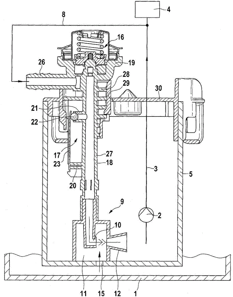
[0011] figure 1 A device for conveying fuel with a drive line component according to a first exemplary embodiment is shown in section.

[0012] The device for delivering fuel is arranged in fuel tank 1 and delivers fuel from fuel tank 1 under increased pressure via pressure line 3 to internal combustion engine 4 by means of a delivery unit 2 , for example an electrically operated fuel pump.

[0013] The delivery unit 2 is arranged in a storage container 5 which maintains sufficient fuel for the delivery unit 2, so that the delivery unit is even in the low-fill state of the fuel tank 1 and when accelerating, braking, cornering and / or Fuel can be pumped when climbing hills.

[0014] From the pressure line 3 of the device branches a drive line 8 which drives a suction jet pump 9 for actively filling the storage container 5 . The drive line 8 can obviously also be supplied with fuel by a return (not shown) of the internal combustion engine 4 or in some other way. The drive line...


PUM


Abstract

A device for conveying fuel is known, having a suction jet pump, a drive line that supplies the suction jet pump with fluid, with a pressure regulating valve arranged in the drive line, the pressure regulating valve being supplied The suction jet pump is only operated above a predetermined pressure in the pressure line of the drive line. A throttle valve downstream of the pressure regulating valve limits the pressure in the drive line. The device according to the invention is improved by integrating the pressure regulating valve and the control valve in the drive line component, so that a cost-effective and compact functional unit results. According to the invention it is provided that in the drive line (8) downstream of the pressure regulating valve (16) a control valve (17) is arranged which limits the pressure in the drive line (8) to a predetermined A certain value, wherein the pressure regulating valve (16) and the control valve (17) are arranged on a common drive line member (18).

Description

technical field [0001] The invention relates to a device for delivering fuel. Background technique [0002] Known by DE 10006622 A1 is a device for conveying fuel with a suction jet pump, a drive line for supplying the suction jet pump with fluid and with a pressure regulating valve arranged in the drive line, which is supplied to the drive line The suction jet pump only operates above a predetermined pressure in the pressure line. A throttle valve downstream of the pressure regulating valve limits the pressure in the drive line. A disadvantage is that the characteristic curve of the pressure regulator is negatively influenced by the pressure as a function of the suction jet pump and the throttle valve. Contents of the invention [0003] On the contrary, the device according to the invention has the advantage that an influence on the characteristic curve of the pressure regulator is avoided by providing a control valve downstream of the pressure regulating valve in the d...

Claims


Application Information

Patent Timeline
Patent Type & Authority Patents(China)
IPC IPC(8): F02M37/02
CPCF02M37/025F02M37/106
Inventor M·拜尔H-P·布劳恩M·屈恩L·屈尔曼
Owner ROBERT BOSCH GMBH
Why Eureka
Try Eureka