Step-down type conversion circuit

一种变换电路、电阻的技术,应用在电气元件、直流功率输入变换为直流功率输出、调节电变量等方向,能够解决操作不便、浪费人力和时间等问题

Inactive Publication Date: 2012-05-30
ZHONGSHAN YUNCHUANG INTELLECTUAL PROPERTY SERVICE CO LTD
View PDF4 Cites 7 Cited by
  • Summary
  • Abstract
  • Description
  • Claims
  • Application Information

AI Technical Summary

Problems solved by technology

However, this method must continuously weld the resistance to the corresponding position of the circuit, which is very inconvenient to operate and wastes a lot of manpower and time

Method used


Image

  • Step-down type conversion circuit
  • Step-down type conversion circuit
  • Step-down type conversion circuit

Examples


Embodiment Construction

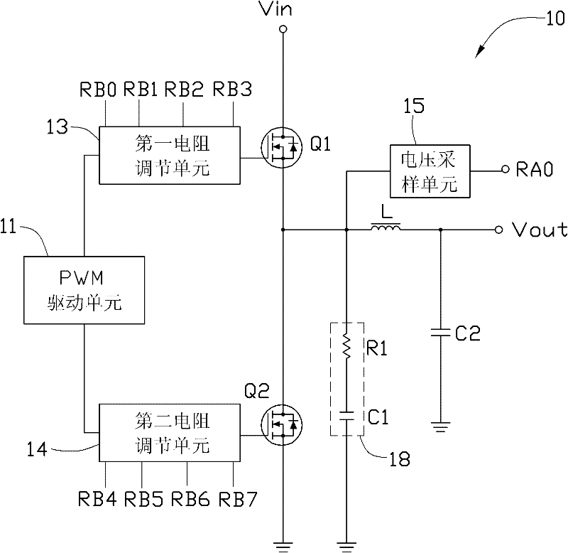
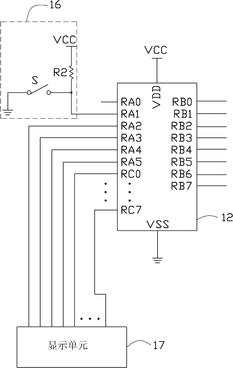
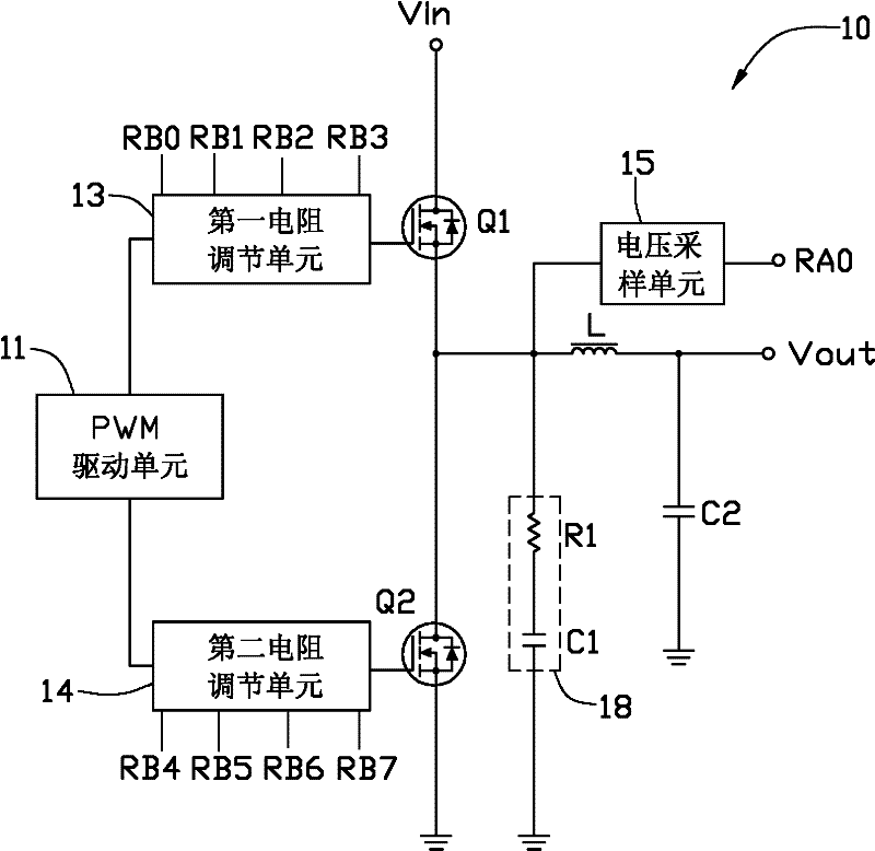
[0039] Please refer to figure 1 and figure 2 A preferred embodiment of the present invention provides a step-down conversion circuit 10, including a voltage input terminal Vin, a PWM (pulse width modulation, pulse width modulation) drive unit 11, a first field effect transistor Q1, a second field effect transistor Q2, a voltage The sampling unit 15 , the control unit 12 , the first resistance adjustment unit 13 , the second resistance adjustment unit 14 , the switch unit 16 , the display unit 17 and the voltage output terminal Vout.

[0040] The voltage input terminal Vin is connected to the drain of the first field effect transistor Q1 to input the external power into the step-down conversion circuit 10 . The source of the first FET Q1 is connected to the drain of the second FET Q2. The drain of the second field effect transistor Q2 is grounded through the inductor L and the second capacitor C2 connected in series. The voltage output terminal Vout is connected between the...


PUM


Abstract

The invention discloses a step-down type conversion circuit. The step-down type conversion circuit comprises a voltage input end, a first field effect transistor, a second field effect transistor, a PWM (Pulse Width Modulation) driving unit, a voltage sampling unit, a first resistance adjusting unit, a second resistance adjusting unit, a control unit and a voltage output end, wherein the first resistance adjusting unit is connected between the PWM driving unit and the gate of the first field effect transistor; the second resistance adjusting unit is connected between the PWM driving unit and the gate of the second field effect transistor; the control unit is connected with the first resistance adjusting unit to change the resistance value of the first resistance adjusting unit; the control unit is connected with the second resistance adjusting unit to change the resistance value of the second resistance adjusting unit; peak voltage between the drain and the source of the second field effect transistor is collected by the voltage sampling unit; and the control unit is connected with the voltage sampling unit to receive an output result of the voltage sampling unit.

Description

technical field [0001] The invention relates to a step-down conversion circuit, in particular to a step-down conversion circuit applied to a computer mainboard. Background technique [0002] The existing step-down conversion circuit (Buck circuit) generally includes a field effect transistor as an electronic switch. However, when the field effect transistor is turned off, oscillation will occur in the circuit, and an excessively high peak voltage Vds will be generated between the drain and the source of the field effect transistor. The spike voltage Vds may cause the field effect transistor to break down, or even damage the field effect transistor. The gate resistance of the FET can be adjusted to adjust circuit parameters and reduce the peak voltage of the FET. [0003] In the existing design, resistors with different resistance values ​​are generally connected to the step-down conversion circuit sequentially manually to obtain the corresponding peak voltage value Vds, an...

Claims


Application Information

Patent Timeline
Patent Type & Authority Applications(China)
IPC IPC(8): H02M3/156
CPCY02B70/1466H02M3/1588Y02B70/10
Inventor 罗奇艳童松林陈鹏
Owner ZHONGSHAN YUNCHUANG INTELLECTUAL PROPERTY SERVICE CO LTD
Why Eureka
Try Eureka