Position signal interference processing method in permanent magnet synchronous motor rotor angle measuring device

A permanent magnet synchronous motor, rotor angle technology, applied in the direction of electronic commutator, etc., can solve the problems of motor controller error command, rotor position error error data, etc., to achieve the effect of overcoming errors or errors and improving safety

Active Publication Date: 2012-05-30
ZHEJIANG GEELY AUTOMOBILE RES INST CO LTD +1
View PDF7 Cites 14 Cited by
  • Summary
  • Abstract
  • Description
  • Claims
  • Application Information

AI Technical Summary

Problems solved by technology

However, the device has no interference processing mechanism. Due to the existence of external interference, the device may cause large errors or even wrong data in the calculated rotor position, which will cause the motor controller to make wrong commands, which may have serious consequences.

Method used


Image

  • Position signal interference processing method in permanent magnet synchronous motor rotor angle measuring device
  • Position signal interference processing method in permanent magnet synchronous motor rotor angle measuring device
  • Position signal interference processing method in permanent magnet synchronous motor rotor angle measuring device

Examples


Embodiment

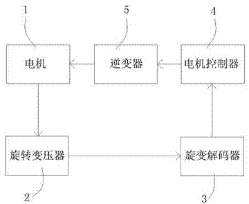
[0020] Such as figure 1 As shown, the motor rotor angle measuring device is composed of a resolver 2, a resolver decoder 3, and a motor controller 4. The resolver 2 is installed on the shaft of the motor 1 and connected to the resolver decoder 3. The resolver decoder 3 is connected to On the motor controller 4, the resolver 4 detects the rotation position of the motor rotor and outputs an analog signal. The resolver decoder 3 is an AU6802N1 decoding chip, and the resolver decoder 3 converts the analog signal into a digital signal, which is resolved by the resolver decoder After the calculation, a 12-bit digital quantity is obtained, which represents the position of the rotor, and the resolver decoder sends the signal to the motor controller. The motor controller 4 analyzes the digital signal to obtain the real-time position and rotational speed of the rotor, and stores the rotor position and rotational speed data,

[0021] The motor controller 4 generates 6 channels of PWM dr...


PUM


Abstract

The invention relates to a position signal interference processing method in a permanent magnet synchronous motor rotor angle measuring device. The angle measuring device comprises a rotary transformer, a rotary transformer decoder and a motor controller. In order to eliminate interference in a measured digital position angle signal, the position signal is processed by the motor controller by adopting median filter and a differential amplitude limiting value, so that the error or fault produced due to interference during angle measurement is effectively overcome, and the safety for engine control is improved.

Description

technical field [0001] The invention relates to a control method in motor rotor position detection, in particular to a position signal interference processing method in a permanent magnet synchronous motor rotor angle measuring device. Background technique [0002] At present, in many automotive motor controller systems, it is necessary to collect the position signal of the rotor in real time and calculate the current speed of the motor. At present, the digital speed measurement sensor in the detection of the rotor position generally uses a resolver, and the resolver outputs an analog signal, and the angle signal is converted into a digital signal through the resolver decoder, and then the digital signal is analyzed by the motor controller to obtain the real-time position of the rotor. position and speed. However, due to the existence of other unpreventable external electromagnetic interference, the digital angular position signal decoded by the resolver decoder does not ne...

Claims


Application Information

Patent Timeline
Patent Type & Authority Applications(China)
IPC IPC(8): H02P6/16H02P6/17
Inventor 陈启苗孙文凯李传海由毅丁勇赵福全
Owner ZHEJIANG GEELY AUTOMOBILE RES INST CO LTD
Why Eureka
Try Eureka