Powered artificial knee with agonist-antagonist actuation

An artificial and dynamic technology, applied in the field of dynamic artificial knee joints, can solve the problems of not being able to replicate the active working phase of human knee joints, and not being able to generate active mechanical energy

Inactive Publication Date: 2012-05-30
MASSACHUSETTS INST OF TECH
View PDF11 Cites 11 Cited by
  • Summary
  • Abstract
  • Description
  • Claims
  • Application Information

AI Technical Summary

Problems solved by technology

While variable damping knees offer some advantages over purely passive knee structures, they cannot generate active mechanical energy and thus cannot replicate the active working phases of the human knee, such as standing-sitting, walking on level ground, and stairs / slopes walk up

Method used


Image

  • Powered artificial knee with agonist-antagonist actuation
  • Powered artificial knee with agonist-antagonist actuation
  • Powered artificial knee with agonist-antagonist actuation

Examples


Embodiment Construction

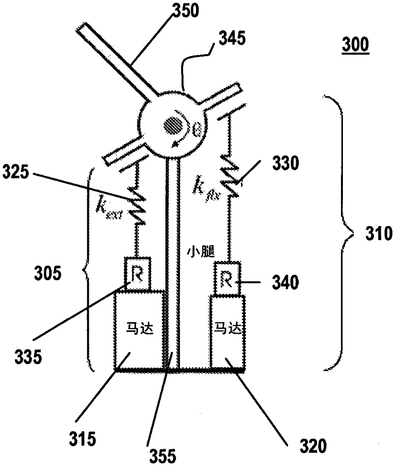
[0035] According to the present invention, a variable damping knee prosthesis has two elastic actuators in series arranged in parallel in a main contractor-antagonist arrangement (arrangement). The prosthetic knee model consists of a variable damper and two elastic clutch units in series across the knee joint. The variable damping control design produces a mechanical structure similar to the human knee when walking on steady-state flat ground. Due to the variable damping properties of the prosthesis, its electrical power requirement during walking is moderate, which allows for an energy-saving dynamic knee. In one application, the variable impedance knee prosthesis according to the invention is advantageously used as part of an untethered (non-restrained) biological robotic leg.

[0036] As used herein, the following terms specifically include, but are not limited to:

[0037] As defined below, "actuator" refers to a type of motor.

[0038] "Primary constrictor" refers to a...


PUM


Abstract

A knee prosthesis comprises an agonist-antagonist arrangement of two series- elastic actuators in parallel, including a knee joint, flexion and extension actuators connected to the joint in parallel with a leg member, and a controller for independently energizing the actuators to control the movement of the knee joint and leg. The flexion actuator comprises the series combination of a flexion motor and a flexion elastic element and the extension actuator comprises the series combination of an extension motor and an extension elastic element. Sensors provide feedback to the controller. The flexion actuator and the extension actuator may be unidirectional, with the flexion and extension elastic elements being series springs. The extension actuator may alternatively be bidirectional, with the extension elastic element being a set of pre-compressed series springs. Alternatively, the flexion elastic element may be a non-linear softening spring and the extension elastic element may be a non-linear hardening spring.

Description

[0001] related application [0002] This application claims priority to US Provisional Application No. 61 / 148,545, filed January 30, 2010, the entire contents of which are hereby incorporated by reference. [0003] This application is a continuation-in-part of co-pending U.S. Patent Application No. 12 / 608,627, filed October 29, 2009, which is U.S. Patent No. 11 / 642,993, filed December 19, 2006 Continuation of Application, Application No. 11 / 642,993, which is now abandoned, claims priority to now expired U.S. Provisional Patent Application No. 60 / 751,680, filed December 19, 2005, and which is listed below Continuation-in-Part of U.S. Patent Application Nos. 11 / 395,448, 11 / 495,140, ​​and 11 / 600,291 and 11 / 499,853 (now U.S. Patent No. 7,313,463), filed August 4, 2005 U.S. Provisional Patent Application No. 60 / 705,651, filed on May 1, 2009, is a continuation-in-part of U.S. Patent Application No. 11 / 395,448 listed below, the entire contents of which are hereby incorporated by refer...

Claims


Application Information

Patent Timeline
Patent Type & Authority Applications(China)
IPC IPC(8): A61F2/62
CPCA61F2/64A61F2002/704A61F2002/74A61F2002/5066A61F2002/7645A61F2002/764A61F2/60A61F2002/7625A61F2/70A61F2002/701A61F2002/5003A61F2/68A61F2002/5072A61F2/74
Inventor H·M·赫尔E·C·马丁内斯-比利亚尔潘多J·A·韦伯
Owner MASSACHUSETTS INST OF TECH
Why Eureka
Try Eureka