Supercharge Your Innovation With Domain-Expert AI Agents!

Obturator valve for a coupling device for pipes

A connection device, obturator technology, applied in the field of obturator valves and devices for connecting pipes, to achieve the effect of enhanced sealing

Inactive Publication Date: 2012-05-30
FMC TECH INC
View PDF5 Cites 0 Cited by
  • Summary
  • Abstract
  • Description
  • Claims
  • Application Information

AI Technical Summary

Problems solved by technology

However, this arrangement has the disadvantage that it requires a strong coupling when rotating the obturator in order to keep said obturator away from the valve seat
As a result, the ball is always preloaded against the valve seat at the moment the rotation begins, and the previously mentioned disadvantages arise

Method used


Image

  • Obturator valve for a coupling device for pipes
  • Obturator valve for a coupling device for pipes
  • Obturator valve for a coupling device for pipes

Examples


Embodiment Construction

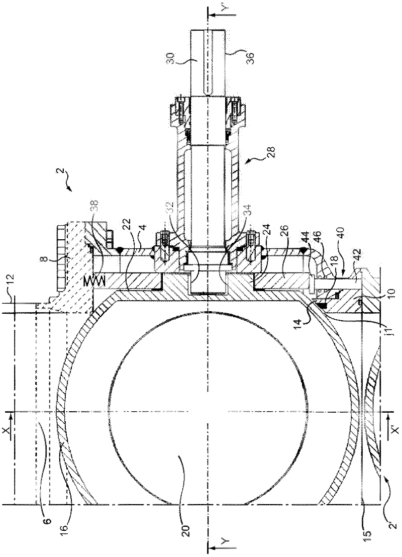
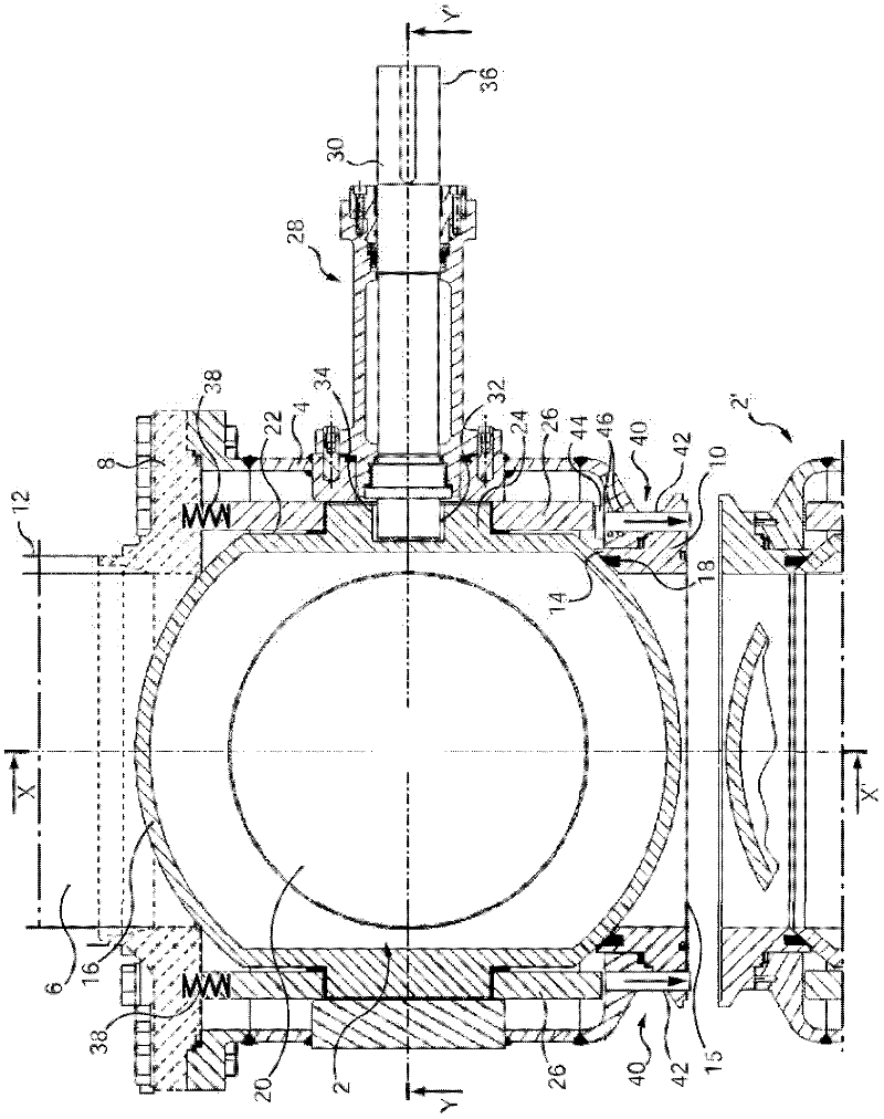
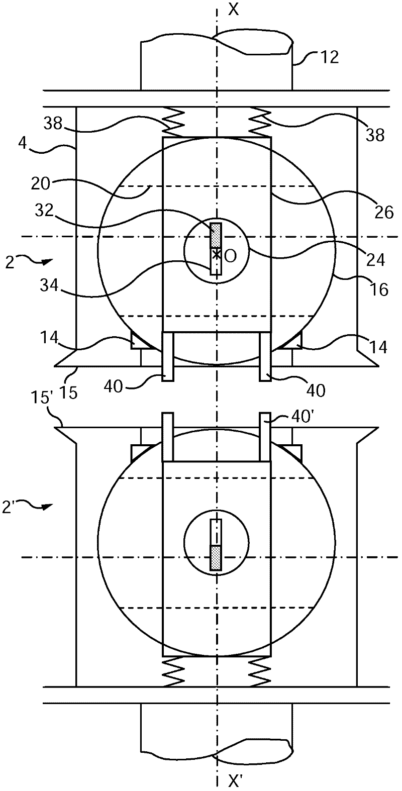
[0039] Figure 1 to Figure 5 The coupling device shown in comprises at least one obturator valve 2 adapted to block and / or allow the passage of fluid from one hydraulic line towards the other hydraulic line.

[0040]The valve 2 is formed by a valve chamber 4, the body of which defines a flow channel 6 extending inside the valve chamber 4 along a first longitudinal axis XX'. According to this first longitudinal axis XX', the valve chamber 4 of the valve 2 has a coupling flange 8 at a first end and a coupling flange 10 at a second end, the flow channel inside the valve chamber 4 6 joins the two flanges 8,10.

[0041] A coupling flange 8 is attached to the valve chamber 4, extends substantially transversely to said valve chamber, and has a coupling end adapted to allow a hydraulic line 12 to be mounted.

[0042] The coupling valve 10 is attached to the valve chamber 4 and forms a valve seat 14 inside the valve chamber. As an example, in the embodiment shown, the valve seat 14 ...


PUM


Abstract

A valve (2) is concerned comprising an obturator (16) maintained in a resting position against a seat (14) through the action of a first force generated by pre not loading means (38), further comprising means (28) for rotating the obturator (16) to place the valve in an open or closed position, characterized in that the valve comprises means (26, 40) for translating the obturator to move the obturator (16) such that a gap (j1 ) is created between the obturator (16) and the seat (14), the translating means being adapted to drive the obturator (16) to move in translation independently of the rotational movement of that obturator (16).

Description

technical field [0001] The invention relates to an obturator valve and a device for connecting pipes, wherein at least a first pipe to be connected is provided with an obturator valve at one end. Background technique [0002] In devices of this type, it is known to drive in rotation an obturator (the obturator can have a disk-like or spherical form) arranged in the valve, to set the obturator in a rotational manner so that the valve corresponds to the An open position through which fluid can pass, or corresponds to a closed position. As an example, when the obturator is a sphere, the flow channel is arranged inside the sphere, and in the open position of the valve the flow channel enables the passage of fluid along the axis of the valve, while in the closed position the flow channel is oriented transverse to fluid passage, and block fluid passage. [0003] The obturator rests in a known manner on a valve seat formed in the valve body. This contact enables the valve to be ...

Claims


Application Information

Patent Timeline
Patent Type & Authority Applications(China)
IPC IPC(8): F16K1/24F16L29/00
CPCF16K5/204F16K1/24Y10T137/6038Y10T137/87933F16K5/06F16K5/20F16L29/00F16L37/08
Inventor D·托特尔C·帕斯泰尔R·勒德维哈
Owner FMC TECH INC
Features
  • R&D
  • Intellectual Property
  • Life Sciences
  • Materials
  • Tech Scout
  • Unparalleled Data Quality
  • Higher Quality Content
  • 60% Fewer Hallucinations
Learn More