Subterranean continuous loop heat exchanger, method of manufacture and method to heat, cool or store energy with same

A heat exchanger, continuous loop technology, used in the field of transferring and/or storing thermal energy

Inactive Publication Date: 2012-05-30
ANZOIC ENERGY
View PDF7 Cites 1 Cited by
  • Summary
  • Abstract
  • Description
  • Claims
  • Application Information

AI Technical Summary

Problems solved by technology

However, more boreholes are required due

Method used


Image

  • Subterranean continuous loop heat exchanger, method of manufacture and method to heat, cool or store energy with same
  • Subterranean continuous loop heat exchanger, method of manufacture and method to heat, cool or store energy with same
  • Subterranean continuous loop heat exchanger, method of manufacture and method to heat, cool or store energy with same

Examples


Embodiment Construction

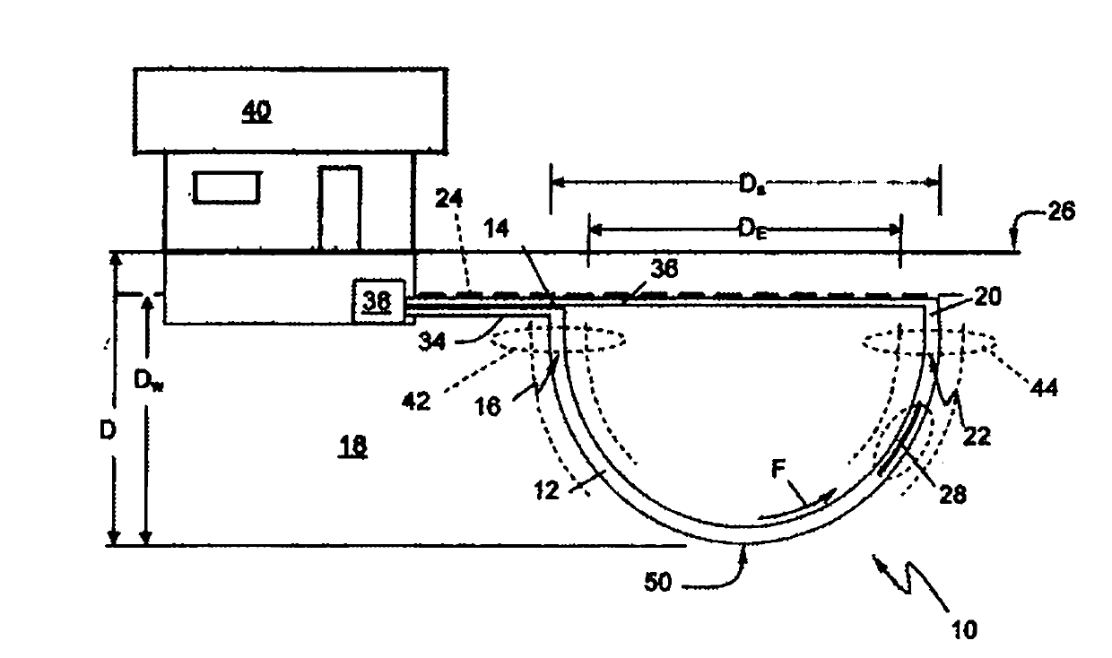
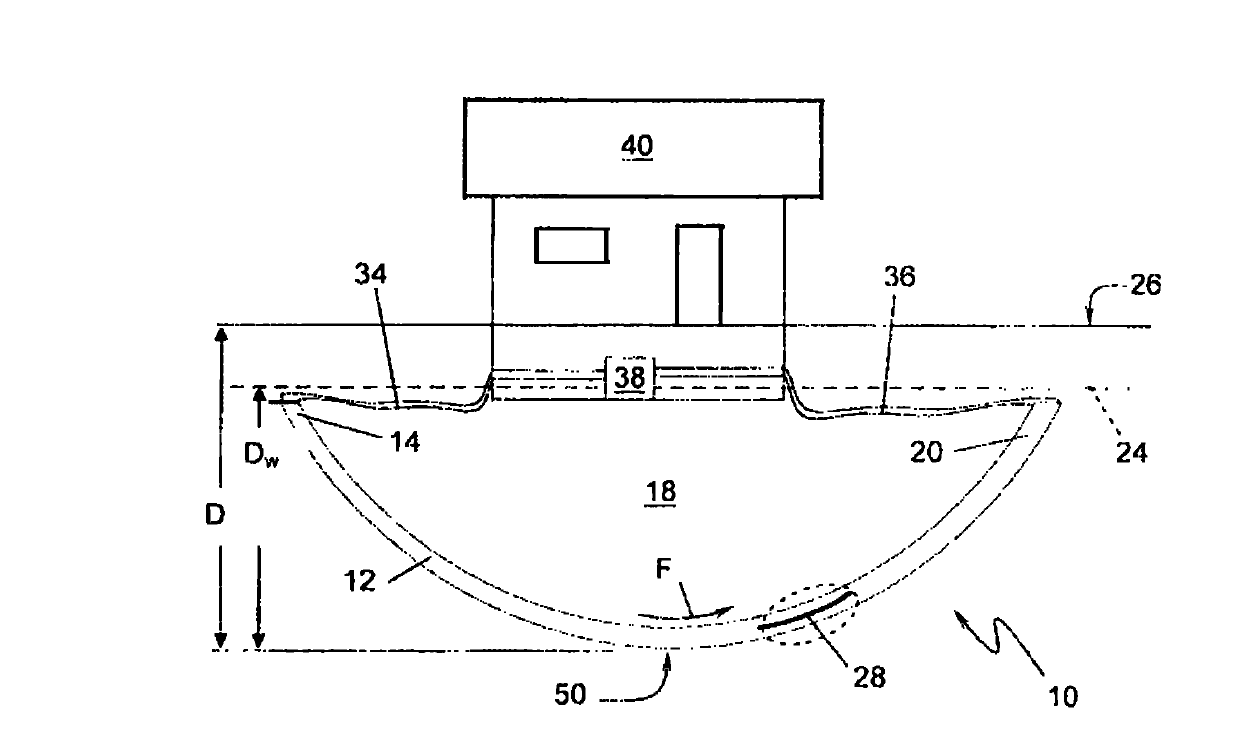
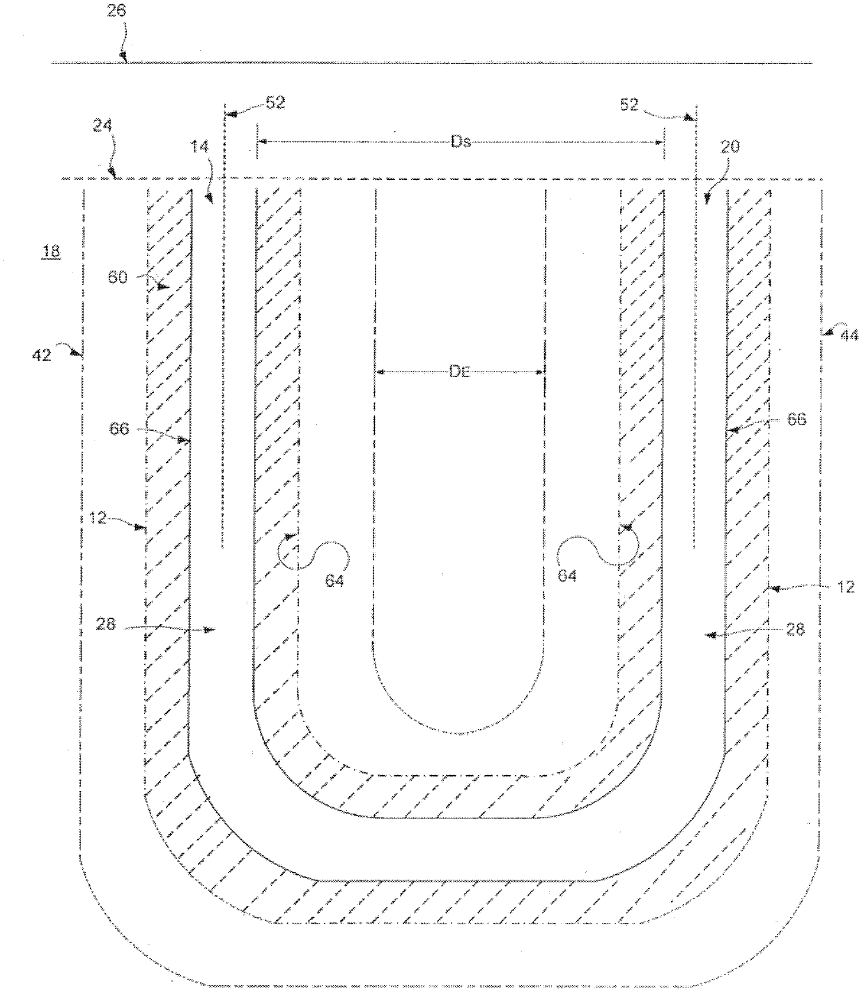
[0048] figure 1 An example embodiment of a subterranean continuous loop heat exchanger is shown having a borehole drilled within a continuous loop through the earth's surface. The subterranean continuous loop heat exchanger 10 includes a borehole 12 including an inlet 14 at a first end 16 and an outlet 20 at a second end 22 where the borehole 12 is at a first Open at a location, such as within the formation 18 for a buried system or on the surface of the formation 18 for a ground system, i.e. on the surface, and at a second end 22, the borehole 12 is open at a second location in the formation 18, such as Openings are made in the formation 18 for buried systems or on the surface of the formation 18 for surface systems, ie on the surface. The majority of borehole 12 is located sufficiently deep below surface level 24 that is susceptible to seasonal temperatures, ie, typically between two and eight feet below surface 26 . A conduit 28 (shown in cross-section) for fluid is locat...


PUM


Abstract

A subterranean continuous loop heat exchanger is disclosed having a borehole including an entrance at a first end and an exit at a second end and a conduit for a fluid. A direction of fluid flow relative to the borehole is unidirectional, and a major length of the borehole is non-horizontal. The entrance and the exit are separated by a predetermined distance and a first thermal envelope at the entrance and a second thermal envelope at the exit are substantially independent. The conduit is positioned in at least a portion of the borehole and in operational connection to supply and return lines for connection to a ground sourced heat pump or to a heat exchanger system. Also disclosed are methods of constructing a subterranean continuous loop heat exchanger having at least one continuous borehole and a method of regulating a temperature in a structure with a system that includes the subterranean continuous loop heat exchanger.

Description

technical field [0001] The present disclosure relates to a heat exchanger, and methods of transferring and / or storing thermal energy. More specifically, the present invention relates to an apparatus and method related to a subsurface heat exchanger having a continuous loop for use in a water based and / or direct exchange system connected to a ground coupled heat pump or providing Underground thermal storage. The heat exchange efficiency of the unidirectional fluid flow through the non-horizontal portion of the subterranean heat exchanger is enhanced, inter alia, by the separation of the thermal enclosure of the system. Background technique [0002] In the discussion of the background below, reference is made to certain structures and / or methods. However, the following citations should not be construed as an admission that these structures and / or methods constitute prior art. Applicant expressly reserves the right to show that such structures and / or methods should not be ad...

Claims


Application Information

Patent Timeline
IPC IPC(8): F24J3/08E21B7/04F25B30/00F28D1/04F28F1/40
CPCF24J3/081E21B7/04Y02E10/12F24J2003/088F24T10/10F24T2010/53F24T2010/56F24T2201/00Y02E10/10Y10T29/4935
Inventor 欧文·霍夫曼
Owner ANZOIC ENERGY
Why Eureka
Try Eureka