Supercharge Your Innovation With Domain-Expert AI Agents!

Image pickup device and method for manufacturing image pickup device

A technology of an imaging device and a manufacturing method, which are applied to radiation control devices, image communication, components of color TV, etc., can solve the problem of difficulty in increasing the strength of the connection between the imaging element 103 and the FPC 110, the size of the front end becoming larger, and the labor And other issues

Inactive Publication Date: 2012-05-30
OLYMPUS CORP
View PDF6 Cites 9 Cited by
  • Summary
  • Abstract
  • Description
  • Claims
  • Application Information

AI Technical Summary

Problems solved by technology

[0015] Therefore, assuming that the imaging device of the second conventional example is installed at the front end of the endoscope, the same Figure 13 In the case of the imaging device 100 in the same way, there is a disadvantage that the size of the longitudinal direction of the front end portion becomes large.
[0016] In addition, in the imaging device 100 of the first conventional example, it is difficult to sufficiently increase the strength of the connection portion between the imaging element 103 and the FPC 110
[0017] In addition, when the first and second imaging devices are installed along the direction in which the optical axis direction of the objective lens system is perpendicular to the longitudinal direction of the tip portion, the radial dimension of the tip portion becomes larger.
[0018] In addition, in the imaging device of the above-mentioned second conventional example, the FPC on which the electronic components are mounted has the characteristics of being easy to process such as bending, and on the other hand, since the amount of bending is set within a predetermined value to avoid that each product There is a possibility of labor-intensive assembly due to adjustment operations that cause deviations, etc.

Method used


Image

  • Image pickup device and method for manufacturing image pickup device
  • Image pickup device and method for manufacturing image pickup device
  • Image pickup device and method for manufacturing image pickup device

Examples


no. 1 approach

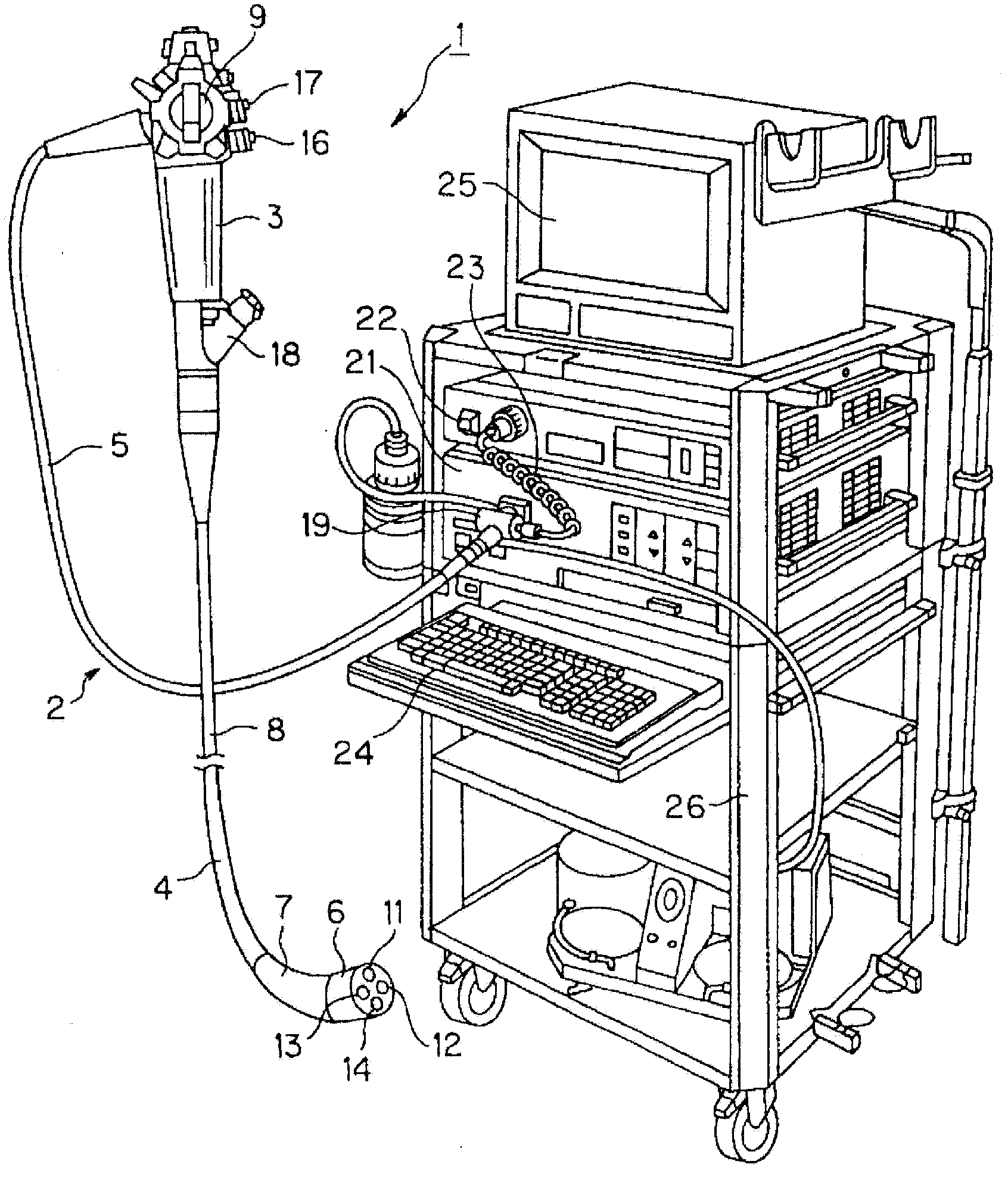
[0056] like figure 1 As shown, an endoscope system 1 for performing endoscopy has an endoscope 2 . The endoscope 2 is composed of the following parts: an operation part 3, which is held and operated by the operator; an elongated insertion part 4, which is formed at the front end of the operation part 3, and is inserted into the body cavity; The base end of the cord 5 extends from the side of the operation part 3 .

[0057] In addition, the insertion part 4 is composed of the following parts: a hard front end part 6, which is provided at the front end of the insertion part 4; a freely bendable bending part 7, which is provided at the rear end of the front end part 6; The tube part 8, which is provided at the rear end of the bent part 7, has flexibility. The bending part 7 can be bent by the bending operation lever 9 provided on the operating part 3 .

[0058] In addition, the front end 6 of the insertion part 4 is provided with: an observation window, which is equipped with...


PUM


Abstract

Disclosed is an image pickup device, which is provided with: a plurality of micro pins, which are provided such that the pins protrude from the rear surface of the image pickup surface of an image pickup element,a plurality of electric substrates, each of which is provided with through holes or penetrating grooves that are formed such that the micro pins can pass through, and which has a substrate surface capable of having an electronic component mounted thereon,and soldering sections where the micro pins and the electric substrates are fixed by means of soldering on land portions adjacent to the through holes or the penetrating grooves, in a state where the electric substrates are stacked on the rear surface of the image pickup element with the micro pins passing through the through holes or the penetrating grooves of the electric substrates.

Description

technical field [0001] The present invention relates to an imaging device including an imaging element mounted on an endoscope or the like, and a method of manufacturing the imaging device. Background technique [0002] In recent years, endoscopes in which an imaging device is attached to the distal end of an insertion portion have been widely used in medical and industrial fields. [0003] Figure 13 The configuration of a conventional imaging device 100 similar to the configuration of the imaging device disclosed in JP 2008-177701 A is shown, which is attached to the distal end portion of an endoscope insertion portion. [0004] The main part of this imaging device 100 is made up of following parts: objective lens system 101, it is made of a plurality of lenses 101a-101f; Lens frame 102, it holds objective lens system 101; Element frame 104, it holds a part of imaging element 103; 105 ; a heat-shrinkable tube 106 ; a protective tube 108 covering the signal cable 107 ; and...

Claims


Application Information

Patent Timeline
IPC IPC(8): H04N5/225A61B1/04A61B1/05G02B23/24H01L27/146
CPCA61B1/042A61B1/05H01L27/14618H04N2005/2255G02B23/2484H01L27/14683H04N5/2253H01L2924/0002G02B23/2469H04N23/54H04N23/555H01L2924/00
Inventor 星一久石田雄也口丸亨山下知晓岩崎诚二正森良辅广谷纯
Owner OLYMPUS CORP
Features
  • R&D
  • Intellectual Property
  • Life Sciences
  • Materials
  • Tech Scout
  • Unparalleled Data Quality
  • Higher Quality Content
  • 60% Fewer Hallucinations
Learn More