Connection block

A technology of connecting blocks and connecting holes, applied in the field of connecting blocks, can solve the problems of complex structure and easy loosening of connecting blocks, and achieve the effect of simple structure and firm fixing

Inactive Publication Date: 2012-06-06
SUZHOU MINGFU AUTOMATIC SCI & TECH
View PDF2 Cites 9 Cited by
  • Summary
  • Abstract
  • Description
  • Claims
  • Application Information

AI Technical Summary

Problems solved by technology

[0002] The rapid development of the industry at this stage has led to the improvement of some mechanical parts. Some mechanical companies are also constantly improving their equipment, but there are still some problems. In the production of machinery, they usual

Method used


Image

  • Connection block
  • Connection block

Examples


Embodiment Construction

[0011] The preferred embodiments of the present invention will be described in detail below in conjunction with the accompanying drawings, so that the advantages and features of the present invention can be more easily understood by those skilled in the art, so as to define the protection scope of the present invention more clearly.

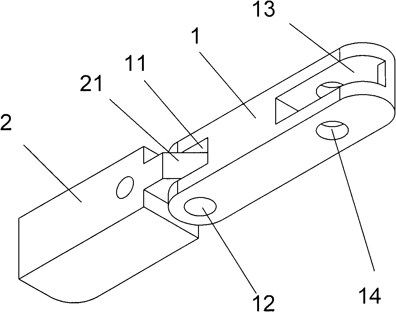
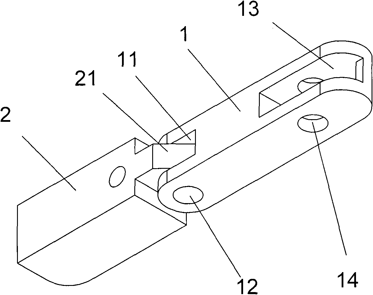
[0012] as attached figure 1 As shown, a connecting block of the present invention includes a front connecting rod 1, a front end head 2 of a shaft positioning seat arranged at one end of the front connecting rod 1, and the front end head 2 of the shaft positioning seat and one end of the front connecting rod 1 move through a pin shaft 12. connect.

[0013] Wherein, the flexible connection between the front end head 2 of the shaft positioning seat and one end of the front connecting rod 1 through the pin shaft 12 is specifically: a protrusion 21 formed at the end of the front end head 2 of the shaft positioning seat, and a protrusion 21 formed at ...


PUM


Abstract

The invention provides a connection block which comprises a front connecting rod (1) and a shaft locator frond end (2) arranged at one end of the front connecting rod (1), wherein, the shaft locator frond end (2) is movably connected with one end of the front connecting rod (1). According to the invention, the front connecting rod of the connection block is movably connected with the shaft locator frond end through a pin, and therefore, the advantages of a simple structure and fixed and firm connection are achieved.

Description

technical field [0001] The invention relates to a connection block. Background technique [0002] The rapid development of the industry at this stage has led to the improvement of some mechanical parts. Some mechanical companies are also constantly improving their equipment, but there are still some problems. In the production of machinery, they usually use Some connecting blocks can rotatably connect the two structures together. This structure is widely used in machinery, but some connecting blocks produced at this stage have more complicated structures and are easy to loosen due to long-term use. take off. Contents of the invention [0003] In order to solve the above technical problems, the present invention provides a connection block with a simple and firm structure. [0004] To achieve the above object, the present invention provides a connecting block, which includes a front connecting rod, a front end of a shaft positioning seat arranged at one end of the front c...

Claims


Application Information

Patent Timeline
IPC IPC(8): F16C11/04
Inventor 庄春明
Owner SUZHOU MINGFU AUTOMATIC SCI & TECH
Why Eureka
Try Eureka