Light source module and stage lighting fixture

A technology for light source modules and lamps, which is applied in the direction of light sources, electric light sources, point light sources, etc., and can solve the problems that the overall volume cannot be reduced, the efficiency of the lighting system is reduced, and the area of ​​the light source is too large.

Inactive Publication Date: 2012-06-06
CORETRONIC
View PDF8 Cites 7 Cited by
  • Summary
  • Abstract
  • Description
  • Claims
  • Application Information

AI Technical Summary

Problems solved by technology

Furthermore, in order to solve the problem of heat dissipation, high-power light-emitting diodes are usually equipped with heat dissipation devices, but the accompanying is that the overall volume cannot be reduced.
Therefore, when users want to increase the brightness output of their lighting system by using multiple LEDs, if these LED arrays are designed on the same plane, there will be a problem of too large light source area, which will reduce the efficiency of the lighting system

Method used


Image

  • Light source module and stage lighting fixture
  • Light source module and stage lighting fixture
  • Light source module and stage lighting fixture

Examples


Embodiment Construction

[0065] The aforementioned and other technical content, features and effects of the present invention will be clearly presented in the following detailed description of preferred embodiments with reference to the accompanying drawings. The directional terms mentioned in the following embodiments, such as: up, down, left, right, front or back, etc., are only referring to the directions of the drawings. Accordingly, the directional terms are used to illustrate and not to limit the invention.

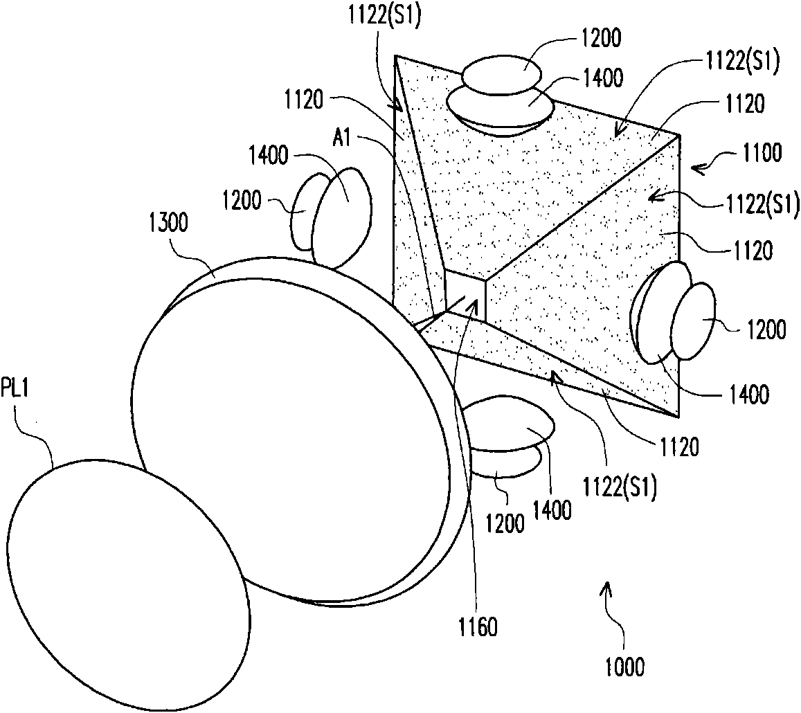
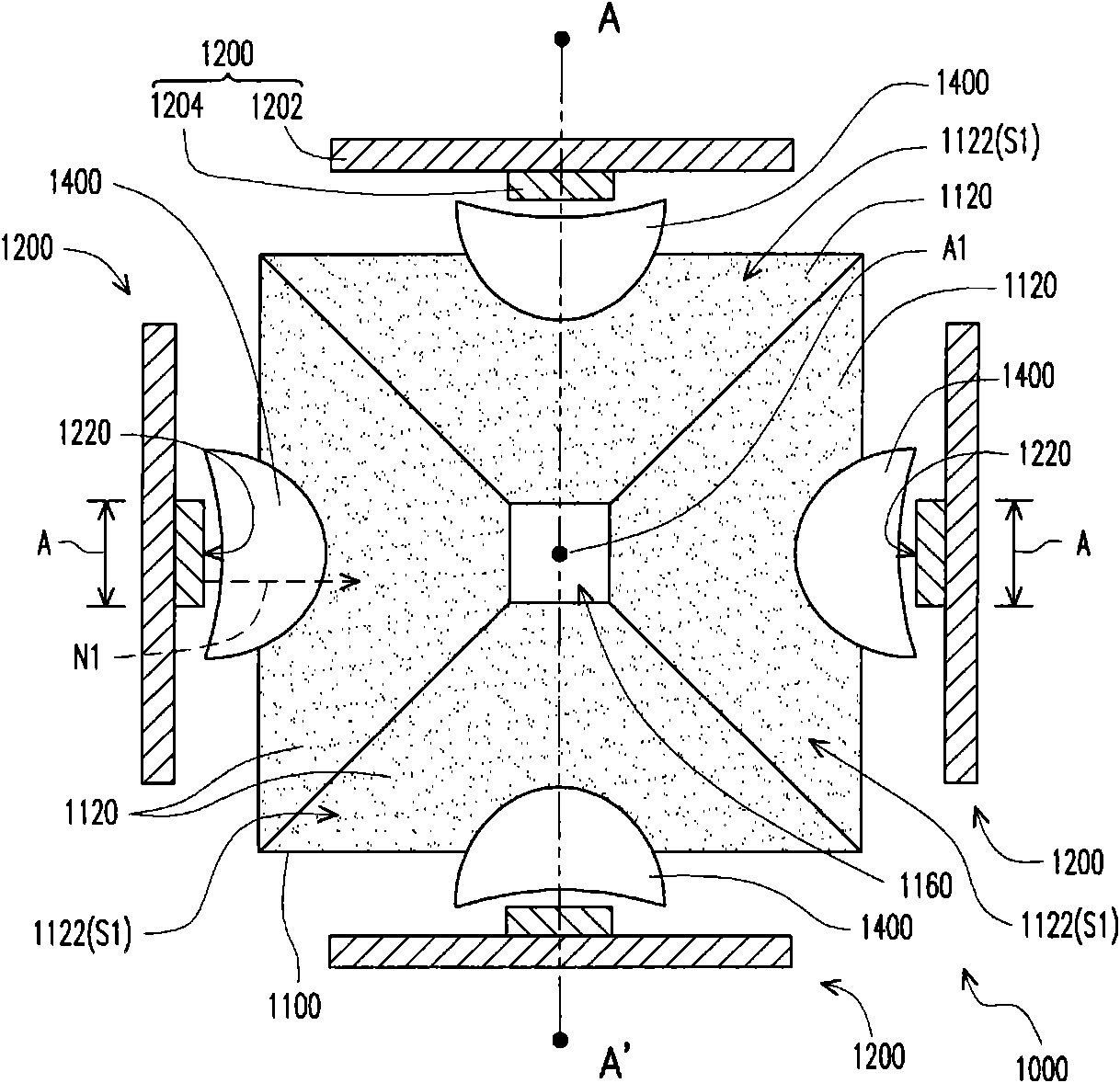
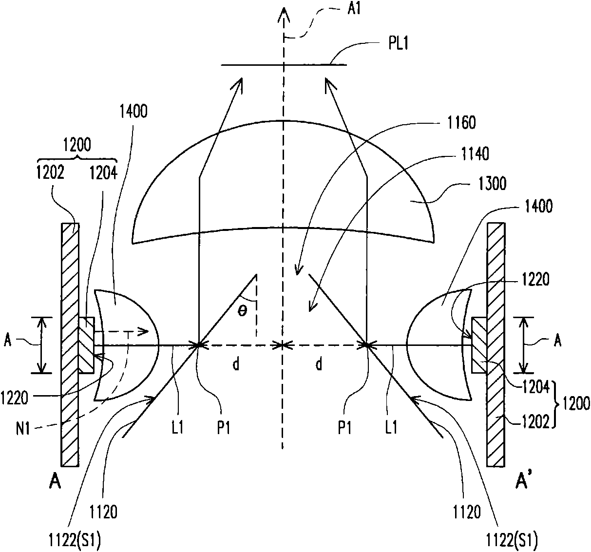
[0066] Figure 1A is a three-dimensional schematic diagram of a light source module according to an embodiment of the present invention, Figure 1B for Figure 1A The schematic diagram of the top view of the light source module, and Figure 1C for Figure 1B A cross-sectional view of the light source module shown by line AA'. Also refer to Figure 1A , Figure 1B and Figure 1C , the light source module 1000 of this embodiment includes a conical reflector 1100 , a plurality of first li...


PUM


Abstract

The invention discloses a light source module, which comprises a conical reflector, a plurality of light-emitting elements and a relay lens. The conical reflector is provided with a central shaft and a plurality of sides which are arranged around the central shaft. The conical reflector comprises a plurality of reflection elements, wherein the reflection elements are respectively provided with a reflection side, and the reflection sides respectively form the sides of the conical reflector. The light-emitting elements are correspondingly arranged at one side of the reflection elements, and are respectively provided with a light-emitting side. The light-emitting side of each light-emitting element is used for providing a light beam. Each reflection side is used for reflecting the light beam which is provided by the corresponding light-emitting side, and each light-emitting side has a light-emitting area. The relay lens is arranged on the transmission path of the light beam which is reflected by the reflection sides, wherein the light source module satisfies the equation that: A/d2 is less than 0.87, wherein d is the distance between the projection position of the first light beam on each reflection side and the central shaft, and A is the first light-emitting area.

Description

technical field [0001] The invention relates to a light source module and a stage lamp, and in particular to a light source module and a stage lamp with small volume, uniform light intensity and concentrated light illumination area. Background technique [0002] In general, high-power LEDs usually have larger packaging volumes to reduce thermal resistance. Furthermore, in order to solve the problem of heat dissipation, high-power light-emitting diodes are usually equipped with a heat dissipation device, but the overall volume cannot be reduced accordingly. Therefore, when the user intends to increase the brightness output of the lighting system by using multiple LEDs, if the LED arrays are designed on the same plane, the problem of too large light source area will occur, thereby reducing the efficiency of the lighting system. Traditionally, in order to eliminate the non-luminous area occupied by the package, the light-emitting diodes can also be placed on different planes, ...

Claims


Application Information

Patent Timeline
Patent Type & Authority Applications(China)
IPC IPC(8): F21S8/00F21V7/10F21V5/04F21V7/04F21V17/00F21V19/00F21Y101/02
Inventor 谢典良
Owner CORETRONIC
Why Eureka
Try Eureka