
Liquid crystal display device

一种液晶显示装置、液晶面板的技术,应用在照明装置、固定照明装置、照明装置的零部件等方向,能够解决成本高、材料成本变高等问题

Active Publication Date: 2012-06-06
PANASONIC INTELLECTUAL PROPERTY CORP OF AMERICA
View PDF6 Cites 6 Cited by
  • Summary
  • Abstract
  • Description
  • Claims
  • Application Information

AI Technical Summary

Problems solved by technology

Therefore, not only the cost of preparing a large number of LEDs is high, but also the material cost of the substrate on which the LEDs are placed becomes high.

Method used


Image

  • Liquid crystal display device
  • Liquid crystal display device
  • Liquid crystal display device

Examples


no. 1 approach

[0062] In addition, this invention is not limited to 1st Embodiment demonstrated above, Various changes are possible.

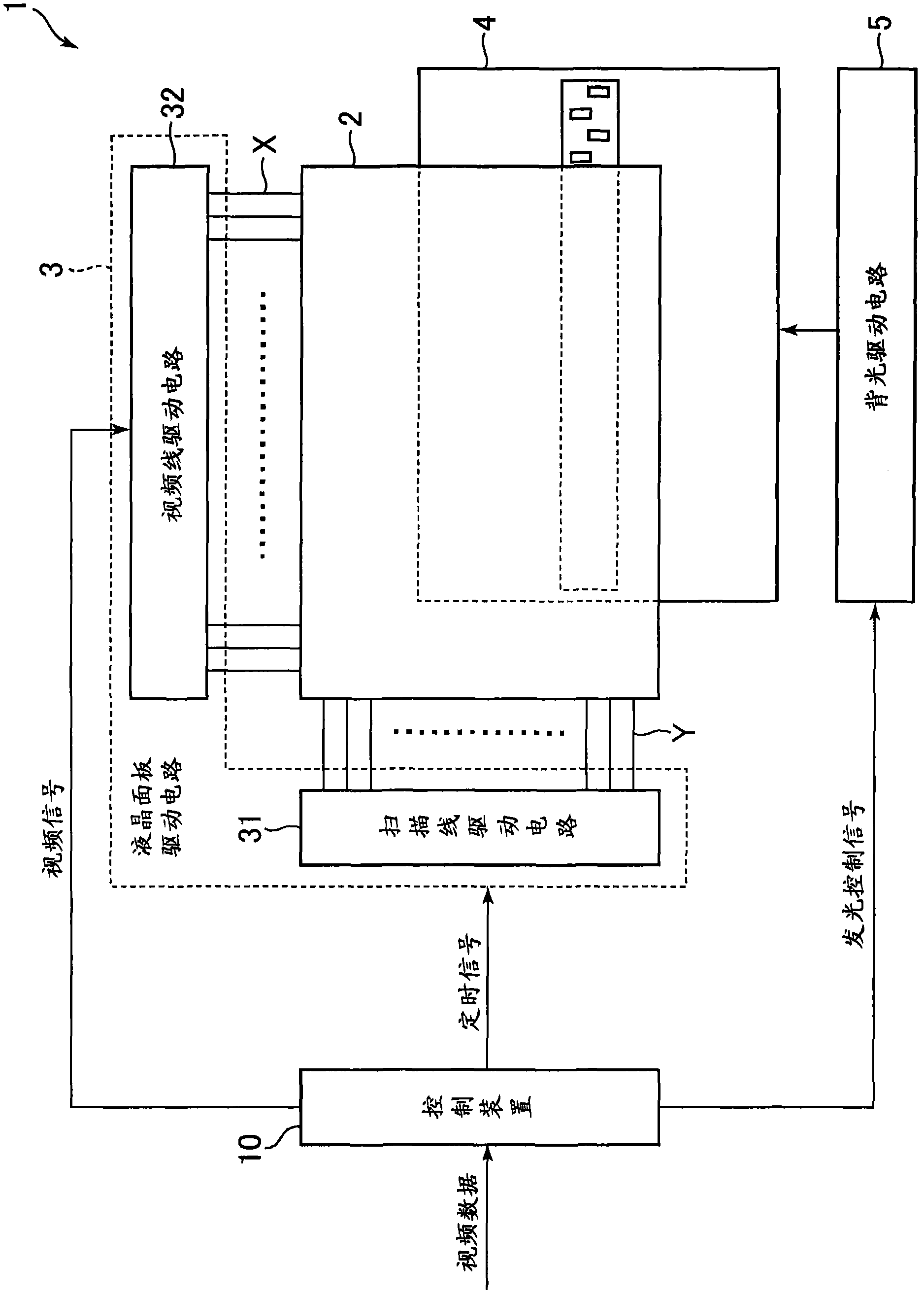
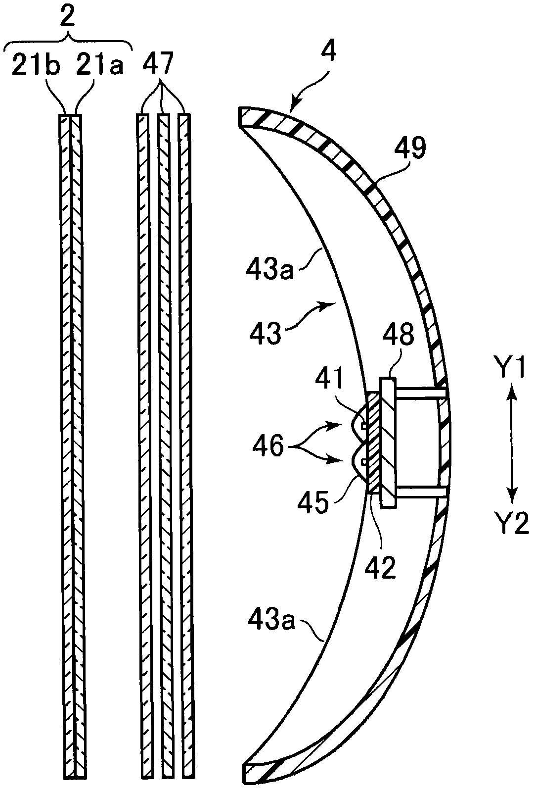
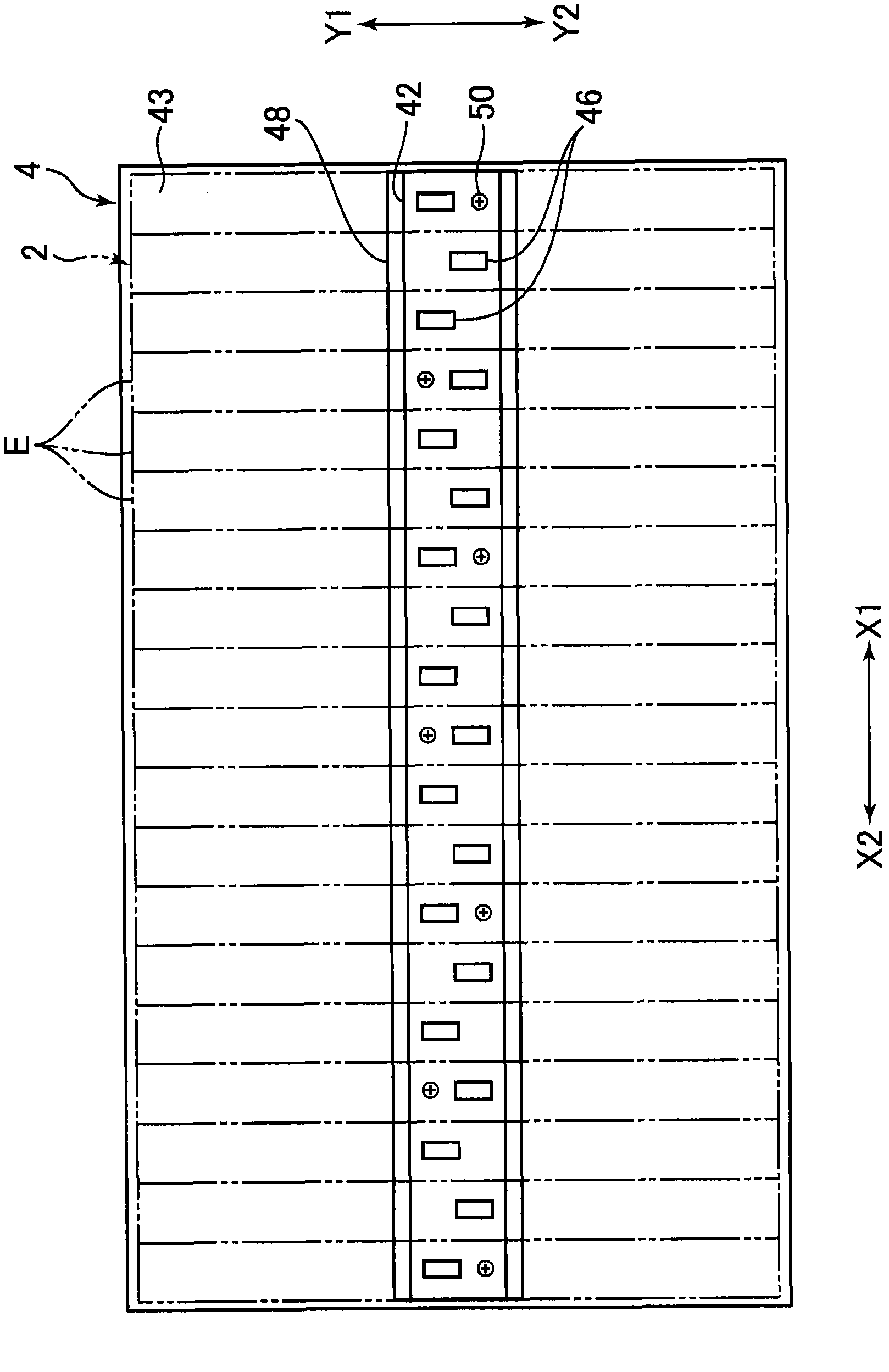
[0063] Next, a second embodiment of the present invention will be described. Figure 8 It is a front view of the backlight unit 4 of the liquid crystal display device 1 according to the second embodiment of the present invention. The difference between the liquid crystal display device 1 according to the present embodiment and the liquid crystal display device 1 according to the first embodiment lies in the arrangement of the LED modules 46 and the mounting parts 50 on the light source substrate 142, and other structures are the same, so the same parts The same reference numerals are assigned, and detailed description thereof will be omitted. in addition, figure 1 and figure 2 It is cited here as a diagram also showing the liquid crystal display device 1 of the present embodiment.

[0064] Such as Figure 8 As shown, in this embodiment, with respect to ...


PUM


Abstract

Provided is a liquid crystal display device (1), including: a liquid crystal panel (2); and a backlight unit (4), which is disposed on a rear surface of the liquid crystal panel (2) and includes a light source substrate (42) onto which a plurality of light sources are mounted and a casing (49), in which: the plurality of light sources are arranged along one direction, and at least one of the plurality of light sources is disposed so as to be offset in a direction orthogonal to the one direction with respect to at least another one of the plurality of light sources; and the backlight unit further includes a fixture (50) for fixing the light source substrate (42) onto the casing (49), the fixture being disposed on a side of the offset light source in an opposite direction to an offset direction.

Description

technical field [0001] The invention relates to a liquid crystal display device. Background technique [0002] JP 2007-286627A discloses a liquid crystal display device having a direct type backlight unit. In the liquid crystal display device described above, a plurality of LEDs (Light Emitting Diodes: Light Emitting Diodes) are used as light sources of the backlight unit. The LEDs are arranged in a grid shape over the entire area of ​​the backlight unit. [0003] In the liquid crystal display device described in JP 2007-286627A, since LEDs are arranged over the entire area of ​​the backlight unit, the size of the substrate on which the above-mentioned large number of LEDs are arranged must be set to cover the entire area of ​​the backlight unit. Therefore, not only the cost of preparing a large number of LEDs is high, but also the material cost of the substrate on which the LEDs are placed becomes high. Contents of the invention [0004] The present invention was made ...

Claims


Application Information

Patent Timeline
Patent Type & Authority Applications(China)
IPC IPC(8): G02F1/13357F21S8/00F21V19/00
CPCG02F1/133603G02F1/133608F21V19/00F21S8/00G02F1/133606G02F1/133607
Inventor 马场匡史
Owner PANASONIC INTELLECTUAL PROPERTY CORP OF AMERICA
Learn More