A side-entry quantum dot backlight module structure

A backlight module and quantum dot technology, applied in optics, nonlinear optics, instruments, etc., can solve the problems of reducing the stability of quantum dots and affecting the service life of the backlight module, so as to improve the service life, enhance the practicability, reduce the The effect of the number of light sources

Active Publication Date: 2022-04-08
FUZHOU UNIV +1
View PDF0 Cites 0 Cited by
  • Summary
  • Abstract
  • Description
  • Claims
  • Application Information

AI Technical Summary

Problems solved by technology

However, for this traditional side-entry quantum dot backlight module, the distance between the light source and the quantum dot layer is relatively close, and the radiation of the light source and the heat generated will reduce the stability of the quantum dots in the quantum dot layer, thus affecting the backlight mode. group life

Method used


Image

  • A side-entry quantum dot backlight module structure
  • A side-entry quantum dot backlight module structure
  • A side-entry quantum dot backlight module structure

Examples


Embodiment 1

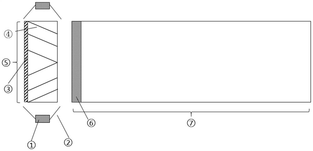
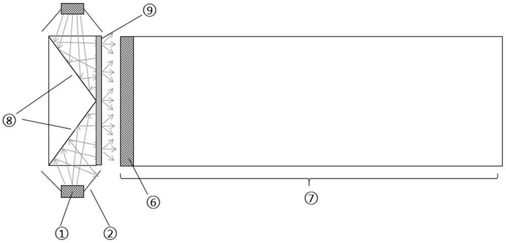
[0029] Such as figure 2 As shown, this embodiment provides a novel side-entry quantum dot backlight module structure, which includes two excitation light sources and their reflectors, an optical path conversion device, and a quantum dot light guide plate. Wherein, the optical path conversion device includes a light transmission medium layer embedded with a reflection sheet, and a light diffusion device is arranged on the light output surface of the light transmission medium layer.

[0030] The excitation light source is a blue light source with a central wavelength of 450nm and a half-peak width of 20nm. The distance between the light source and the end surface of the optical path conversion device is 0.1 mm, and a reflector is arranged outside the light source, and the opening of the reflector is larger than the light-emitting area of ​​the light source. The thickness of the light source light-emitting unit is slightly smaller than the thickness of the optical path conversi...

Embodiment 2

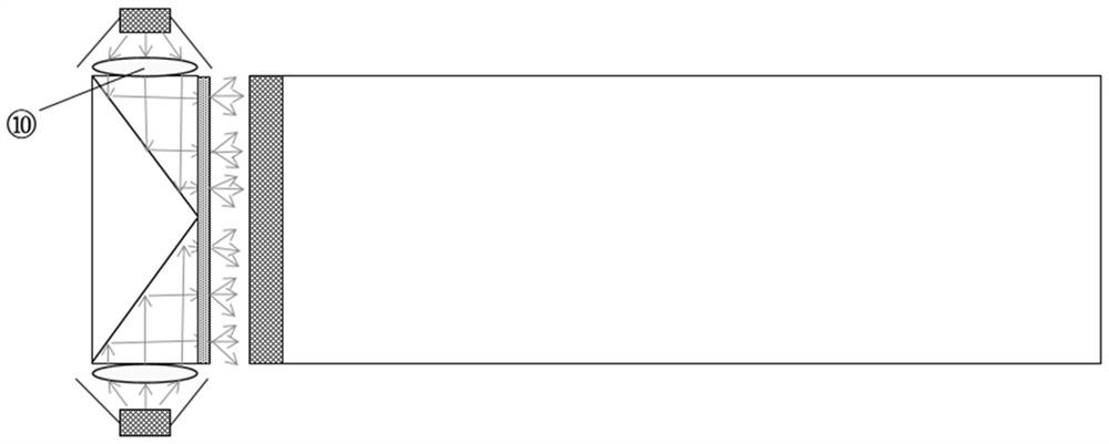
[0034] Such as image 3 As shown, two convex lenses are introduced into the above structure, and the convex lens is arranged on the end surface of the light transmission medium layer, and the exciting light source is arranged at the focal point of the convex lens, so that the scattered light emitted from the light source becomes parallel light after passing through the convex lens, parallel light Can be more easily controlled and emitted into the light guide plate.

Embodiment 3

[0036] Such as Figure 4 As shown, this embodiment provides a novel side-entry quantum dot backlight module structure, which includes two excitation light sources and their reflectors, an optical path conversion device, and a quantum dot light guide plate. Wherein, the optical path conversion device includes a light transmission medium layer embedded with a reflective sheet, a light diffusion device is provided on the light exit surface of the light transmission medium layer, and a reflective coating is provided on the corresponding surface of the light exit surface of the light transmission medium layer.

[0037] The excitation light source is a blue light source with a central wavelength of 450nm and a half-peak width of 20nm. The distance between the light source and the end surface of the optical path conversion device is 0.1 mm, and a reflector is arranged outside the light source, and the opening of the reflector is larger than the light-emitting area of ​​the light sour...


PUM


Abstract

The invention relates to a side-entry quantum dot backlight module structure, which includes two excitation light sources provided with reflectors, an optical path conversion device and a quantum dot light guide plate, and the excitation light sources are respectively located on the left and right sides of the optical path conversion device , the optical path conversion device is located on the side of the quantum dot light guide plate, and the light incident side of the quantum dot light guide plate has a quantum dot layer; a part of the light emitted by the excitation light source is incident on the quantum dot light guide plate after being reflected by the optical path conversion device , after the color conversion of the quantum dot layer and the modulation of the quantum dot light guide plate, the light is emitted, and the other part of the light that is directed to the reflector after passing through the optical path conversion device is incident on the quantum dot again after being reflected by the reflector and the action of the optical path conversion device. Reuse in the light guide plate. This structure can not only effectively reduce the influence of light radiation and light source heat on the quantum dots, improve the service life of the backlight module, but also greatly reduce the number of light sources used in the backlight module and reduce production line costs.

Description

technical field [0001] The invention belongs to the field of display technology, and in particular relates to a side-entry quantum dot backlight module structure. Background technique [0002] With the development of display technology, liquid crystal display has become the most mature and widely used display device among many flat-panel display devices, which is still developing rapidly. LCD has the advantages of light and thin, low energy consumption, soft picture, and good heat dissipation. With the continuous decline of LCD manufacturing costs, it is widely used in display products such as mobile phones, tablets, and TVs. At present, the color gamut of most LCDs is around 78% NTSC color gamut. Compared with the wide color gamut, the display effect is poor, especially when the red area is displayed, it often gives people a sense of distortion. Recently, due to the narrow emission spectrum of quantum dots, easy control of emission spectrum, high quantum yield, wide absorp...

Claims


Application Information

Patent Timeline
Patent Type & Authority Patents(China)
IPC IPC(8): G02F1/13357
CPCG02F1/133615
Inventor 陈恩果蔡俊虎江宗钊王晨辉徐胜叶芸郭太良
Owner FUZHOU UNIV
Why Eureka
Try Eureka