Freight car capable of automatically deforming
A technology for carriages and trucks, which is applied to the upper structure of trucks, vehicle components, upper structures, etc. It can solve problems such as parking difficulties and traffic congestion, and achieve the effects of saving parking space, alleviating traffic congestion, and smooth driving at high speeds
- Summary
- Abstract
- Description
- Claims
- Application Information
AI Technical Summary
Problems solved by technology
Method used
Image
Examples
Embodiment 1
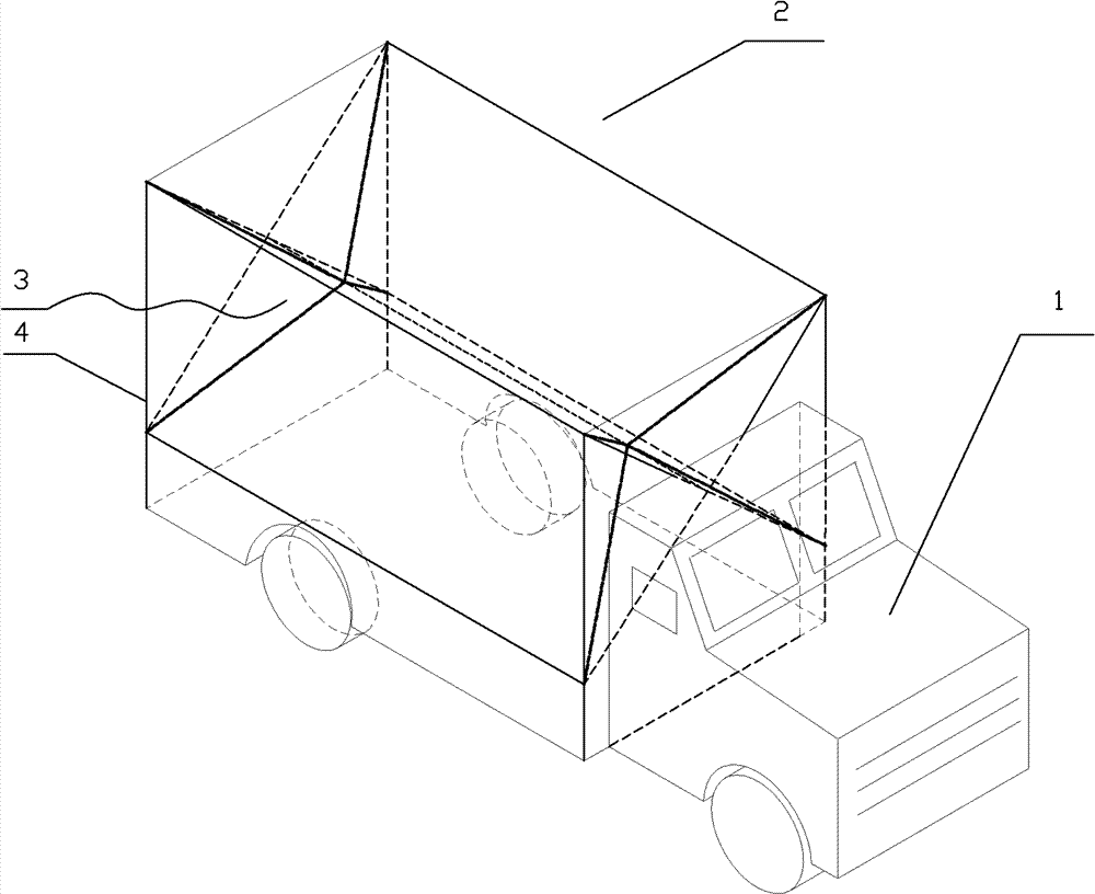
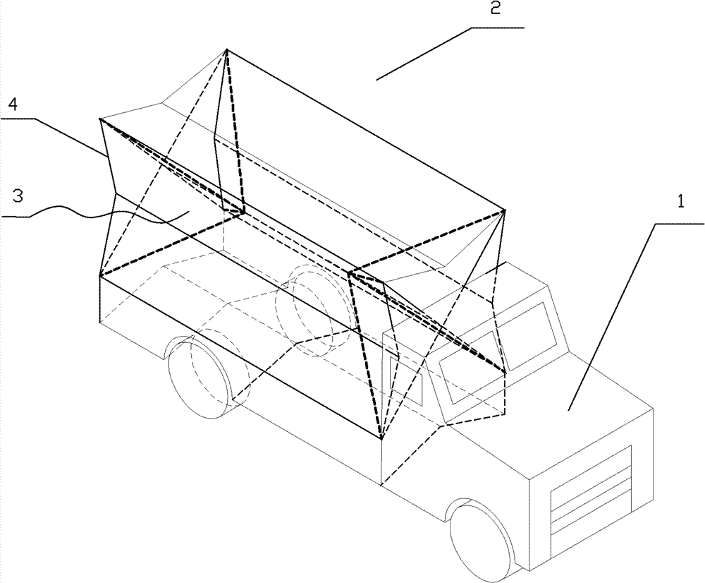
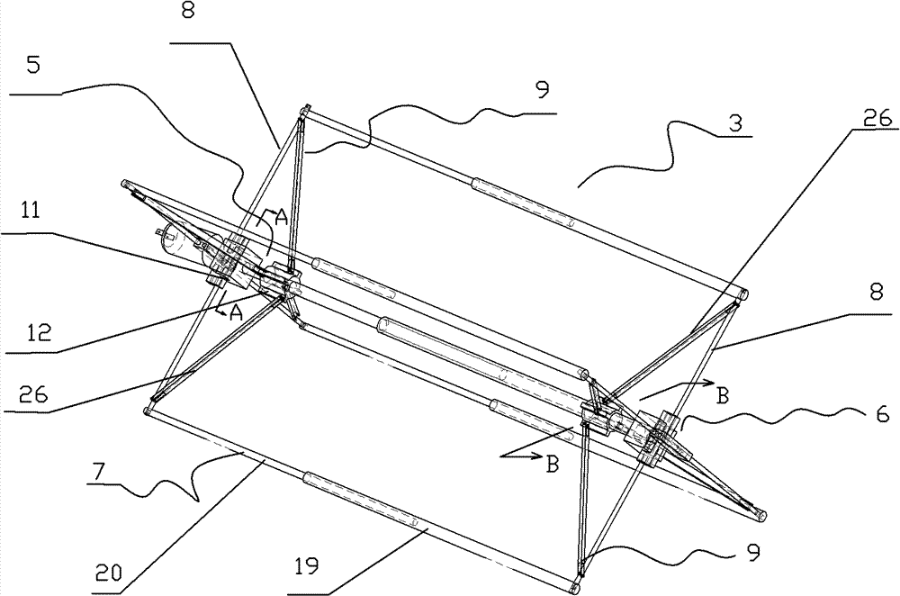
[0033] Such as figure 1 The small truck shown includes a headstock 1 and a compartment 2, and the compartment 2 is composed of a compartment frame 3 and a compartment wall 4. Such as image 3 As shown, the carriage frame 3 includes a main rod assembly 5 , a double slider assembly 6 , a side rod assembly 7 , a slide rod 8 , and a tie rod assembly 9 . The carriage frame 3 supports the carriage wall 4, and each surface of the carriage wall 4 can be folded.
[0034] Such as Figure 5 As shown, the main rod assembly 5 adopts the principle of a roller screw. The main rod assembly 5 includes left and right motors 11, 11', left and right threaded rods 10, 10', left small sleeve 14, right large sleeve 14', left and right main rod sliders 12, 12'. The motors 11, 11' are respectively placed in the motor bases 22, 22', the outer ends of the motor bases 22, 22' are fixedly connected with the double slider assembly 6, and the motors 11, 11' can drive the threaded rods 10, 10' to rotate....
Embodiment 2
[0043] The difference from Embodiment 1 is the main rod assembly 5 of the carriage frame 3 assembly.
[0044] Such as Figure 8 As shown, the main rod assembly 5 includes a fixed rod 27, a motor 11, a fixed slideway 28, an upper rack 29 and a lower rack 29' with opposite threads. The outer ends of the upper and lower racks 29,29' are respectively fixed on the main rod slider 12,12', and the main rod slider 12,12' can slide freely on the fixed rod 27 simultaneously. The outer end of the fixed rod 27 is fixedly connected with the double slider assembly 6 , and the inner end is provided with a fixed slideway 28 . combine Figure 9 As shown, the fixed slideway 28 is provided with a motor 11, and the inner ends of the two racks 29, 29' can freely pass through the two holes of the fixed slideway 28 and mesh with the motor gear 30 in the motor 11. The left end of tooth bar 29 ' is without sawtooth.
[0045] When the motor 11 rotates and the two racks move toward each other, the t...
Embodiment 3
[0048] combine Figure 10 , 11 As shown, on the coaxial side of the large motor gear 30, a small gear 30' is added. The upper rack 29 meshes with the pinion 30'.
[0049] When the bull gear 30 and the pinion 30' rotate, they drive the upper rack 29 and the lower rack 29' respectively, and the upper and lower racks drive the pull rod 26 to realize the shrinkage of the width and height of the compartment 2. Since the linear velocity of the large gear 30 is greater than that of the pinion 30', the moving speed behind the carriage 2 is slower than the moving speed at the front. Therefore, as figure 2 As shown, when the width and height of the compartment 2 are flexible, the length is also flexible.
PUM
 Abstract
Description
Claims
Application Information
 - R&D
- Intellectual Property
- Life Sciences
- Materials
- Tech Scout
- Unparalleled Data Quality
- Higher Quality Content
- 60% Fewer Hallucinations
Browse by: Latest US Patents, China's latest patents, Technical Efficacy Thesaurus, Application Domain, Technology Topic, Popular Technical Reports.
© 2025 PatSnap. All rights reserved.Legal|Privacy policy|Modern Slavery Act Transparency Statement|Sitemap|About US| Contact US: help@patsnap.com


