
Special metal wire twisting machine

A twisting machine and metal wire technology, applied in the field of twisting devices, can solve the problems of unsynchronized pay-off of core wire and upper thread, inconvenient adjustment of wire width and tension, poor versatility and interchangeability, etc. Improve operation safety performance, compact structure, convenient installation and maintenance

Inactive Publication Date: 2012-06-13
江苏金泰隆机电设备制造厂
View PDF7 Cites 23 Cited by
  • Summary
  • Abstract
  • Description
  • Claims
  • Application Information

AI Technical Summary

Problems solved by technology

[0002] Existing metal wire twisting equipment with 3+9×0.175, 3+9×0.22, 3+8×0.22HT HC structures are not only imported, but domestically manufactured equipment has the following disadvantages: 1. The core wire and the upper wire are separated The wire is unwound, and then twisted into a cord by an external wire collection mechanism, which increases the use of equipment, takes up space, and high cost of use; 2. The flywheel slider installed on the steel flywheel disc, the metal wire moves up and down, and it is easy to get out of the slider. Flying out; 3. There is no speedometer or the motor does not have an encoder, which causes the core wire pay-off and the upper thread pay-off to be out of sync; 4. The take-up and arranging wires are arranged by a screw rod, and the adjustment of the wire width and tension is inconvenient. poor interchangeability

Method used


Image

  • Special metal wire twisting machine
  • Special metal wire twisting machine
  • Special metal wire twisting machine

Examples


Embodiment Construction

[0022] The present invention will be further described below in conjunction with drawings and embodiments.

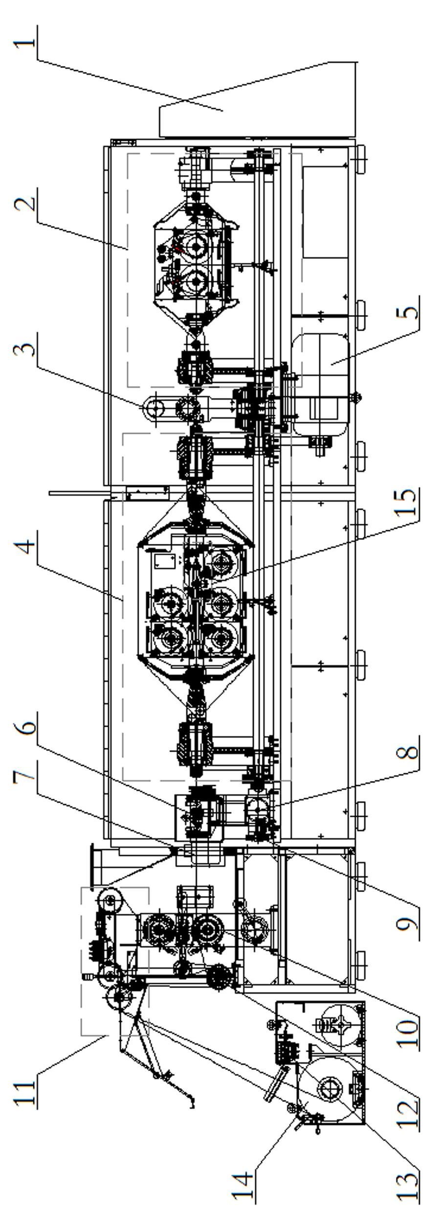
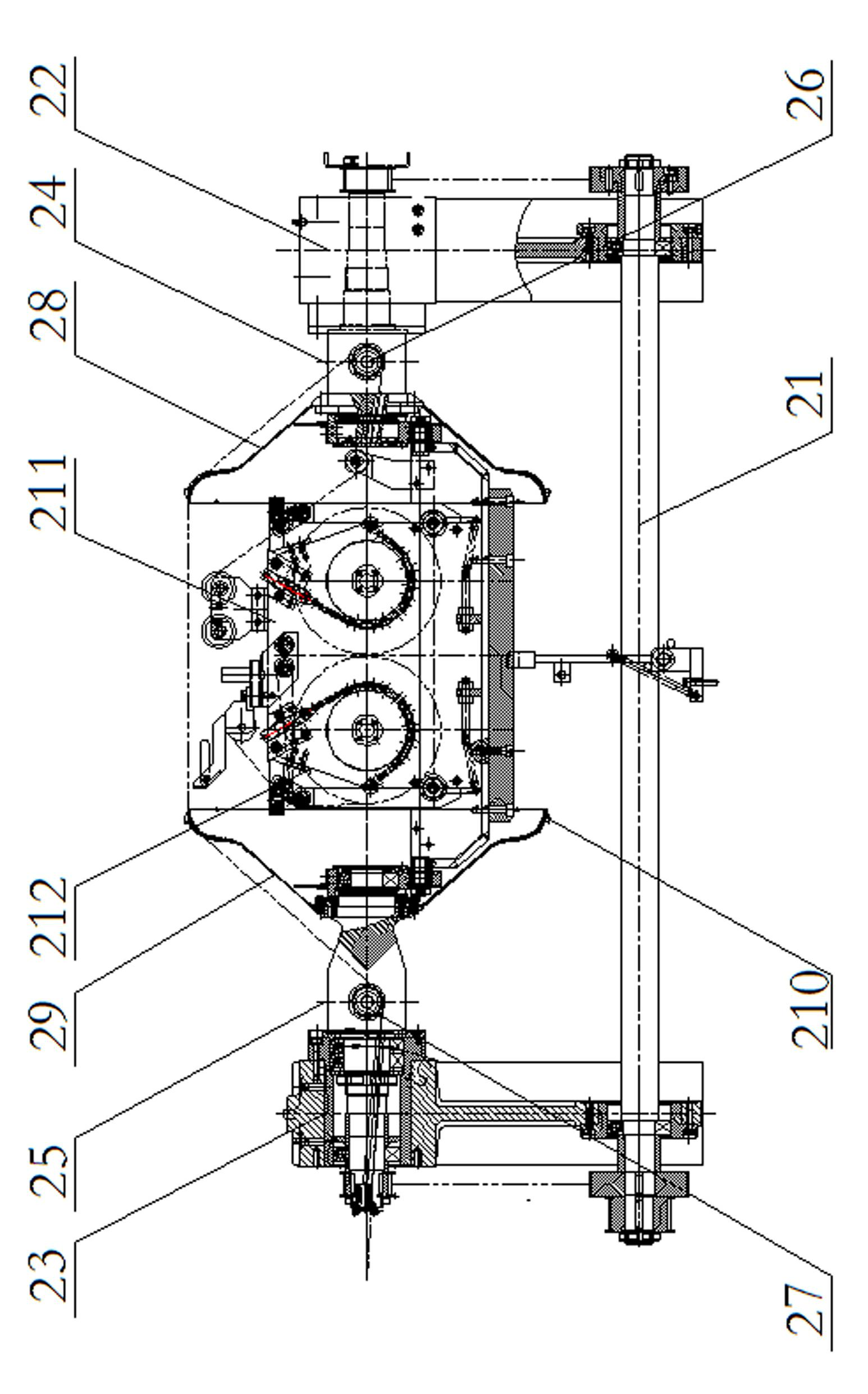
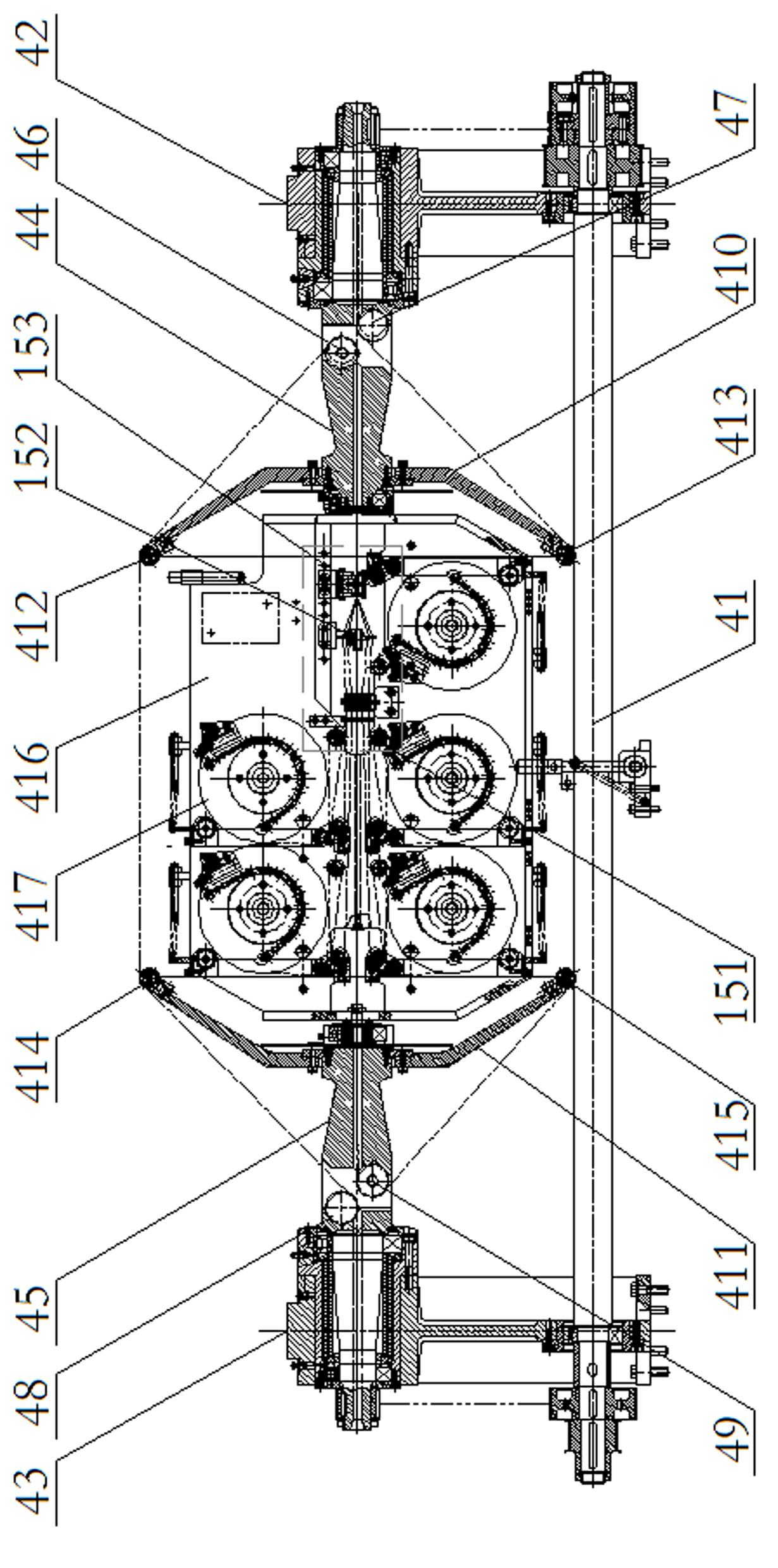
[0023] Figure 1-3 As shown, a special wire twisting machine includes a control cabinet 1, a wire pay-off assembly 2, a wire tension bridge assembly 3, an upper thread pay-off assembly 4, a main motor 5, an over-twisting assembly 6, a frequency conversion Motor 7, speed reducer 8, speed detector 9, traction mechanism 10, meter counter 11, straightener 12, electromagnetic cable puller 13, wire take-up mechanism 14 and wire collection mechanism 15. The wire pay-off assembly 2, the wire tension bridge assembly 3, and the upper thread pay-off assembly 4 are all arranged in the soundproof safety cover; the core wire pay-off assembly 2 includes a core wire drive shaft 21, front and rear core wire flying Axle assemblies 22, 23, front and rear core wire flywheel discs 28, 29, core wire cradle frame 210 and a plurality of core wire I-shaped wheels 212, the main motor 5 is c...


PUM


Abstract

The invention relates to a special metal wire twisting machine which mainly consists of a core wire and a surface wire pay-off rack, a core wire cradle K30, a core wire transmission assembly, a core wire tension and bridge assembly, a surface wire cradle K90, a surface wire transmission assembly, an over-twisting mechanism, a speed reducer, a speedometer, a traction mechanism, a meter counter, a straightening device, a wire arranging and take-up mechanism, a main motor and an electric control cabinet. The twisting mechanism has a compact structure, causes low noise, is stable in operation, is convenient to install and maintain, ensures table product quality, and can produce cores of 3+9*0.175, 3+9*0.22 and 3+8*0.22HTHC.

Description

technical field [0001] The invention relates to a twisting device for twisting cord strands, which is a special wire twisting machine for producing steel cords for light truck tires, semi-finished cords for truck tires and high-strength cords. Background technique [0002] Existing metal wire twisting equipment with 3+9×0.175, 3+9×0.22, 3+8×0.22HT HC structures are not only imported, but domestically manufactured equipment has the following disadvantages: 1. Core wire and upper wire are separated 2. The flywheel slider installed on the steel flywheel disc, the metal wire moves up and down, and it is easy to get out of the slider. Flying out; 3. There is no speedometer or the motor does not have an encoder, which causes the core wire pay-off and the upper thread pay-off to be out of sync; 4. The take-up and arranging wires are arranged by a screw rod, and the adjustment of the wire width and tension is inconvenient. Interchangeability is poor. Contents of the invention ...

Claims


Application Information

Patent Timeline
IPC IPC(8): D07B3/00D07B7/02D07B7/06D07B7/10
Inventor 钱泽兰黄义华吴兰美周树民
Owner 江苏金泰隆机电设备制造厂
Learn More