Construction method for circular foundation bolt hole reserved for equipment foundation

A technology of equipment foundation and construction method, which is applied in the direction of basic structure engineering, formwork/formwork/working frame, and on-site preparation of building components. Achieve the effects of reducing labor intensity, improving pull-out bearing capacity, and reducing construction costs

Active Publication Date: 2014-07-02
CHINA FIRST METALLURGICAL GROUP
View PDF5 Cites 0 Cited by
  • Summary
  • Abstract
  • Description
  • Claims
  • Application Information

AI Technical Summary

Problems solved by technology

The steel corrugated pipe adopts a tool with a slot at one end and a handle at the other end. The slot is clamped to the steel bellows, and the steel corrugated pipe is peeled off layer by layer. The removal effect is not satisfactory; the plastic pipe is baked at high temperature to make it soft, and then Pulling out as a whole, the method sometimes causes the plastic pipe to break off, which directly affects the strength of the secondary grouting of the anchor bolt holes; the wooden formwork adopts a square pyramid-shaped wooden box structure with a large upper opening and a smaller lower opening, with small cross-section and deep depth. For deep holes, there will be various difficulties such as difficulty in force and limited space when dismantling
In order to improve the pull-out bearing capacity of bolts, a structure with the lower opening slightly larger than the upper opening is often used. Steel bellows and plastic pipes are standard materials, which cannot meet the requirements. requirements, and cannot be removed
Namely: the anchor bolt hole is characterized by a long and narrow space with a large aspect ratio, so it brings great inconvenience to the demolition, and its formwork cannot be reused during the demolition process

Method used


Image

  • Construction method for circular foundation bolt hole reserved for equipment foundation
  • Construction method for circular foundation bolt hole reserved for equipment foundation
  • Construction method for circular foundation bolt hole reserved for equipment foundation

Examples


Embodiment Construction

[0024] In order to better understand the present invention, the technical solutions of the present invention will be further described below in conjunction with the embodiments and the accompanying drawings.

[0025] The construction method of reserving circular anchor bolt holes for the equipment foundation includes the following steps:

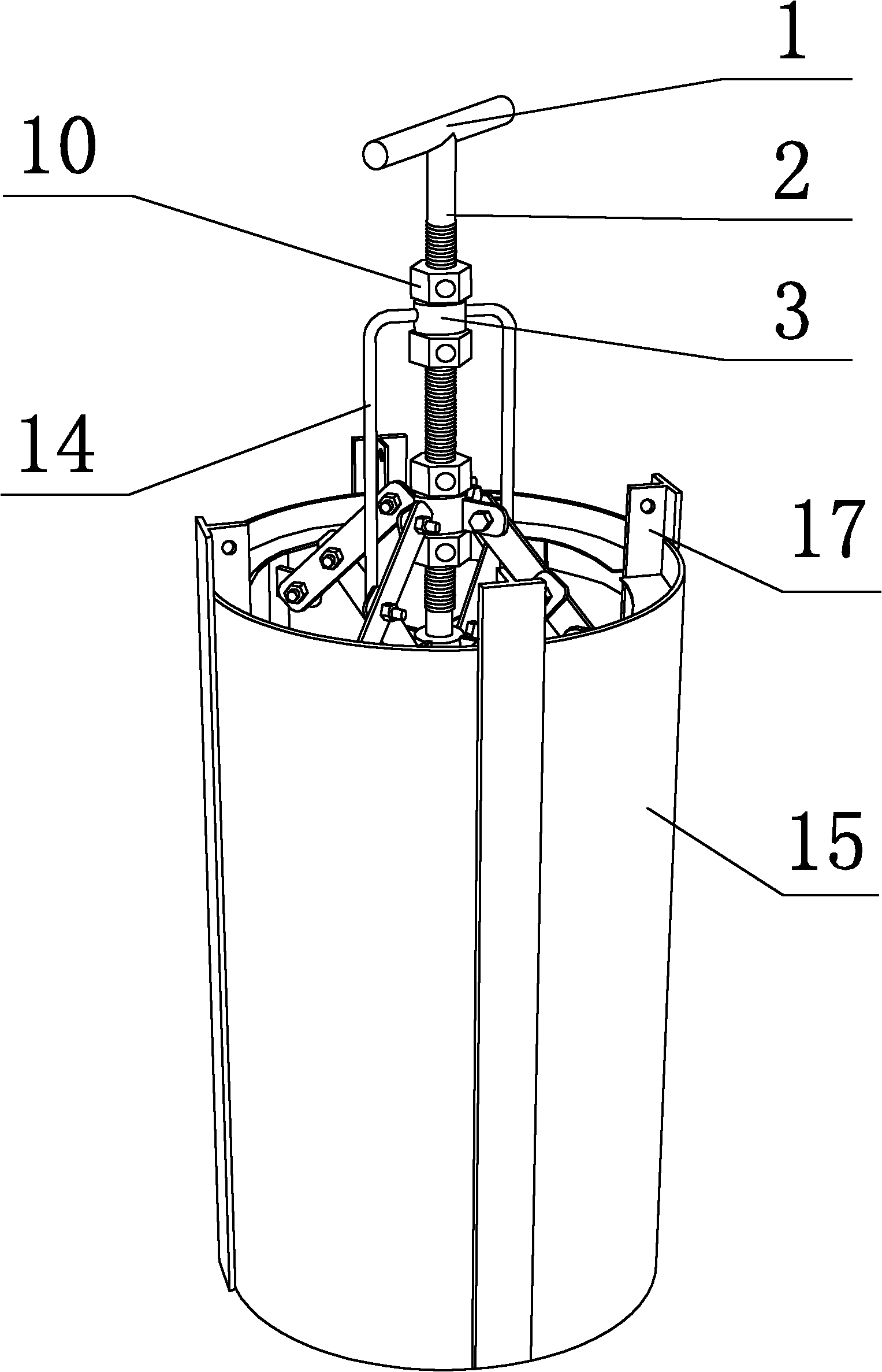
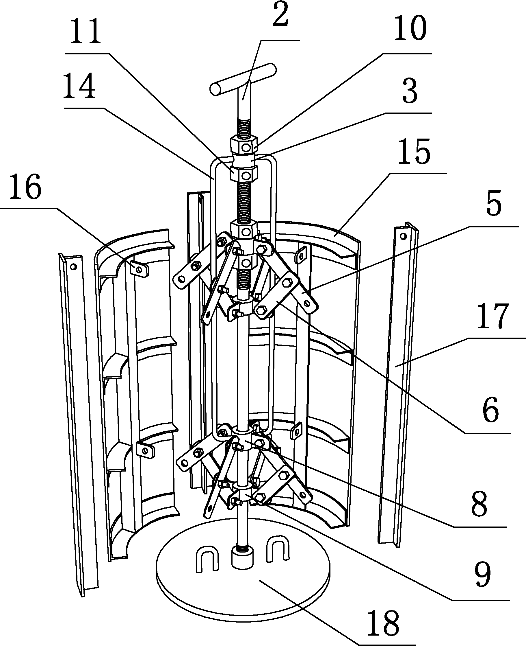
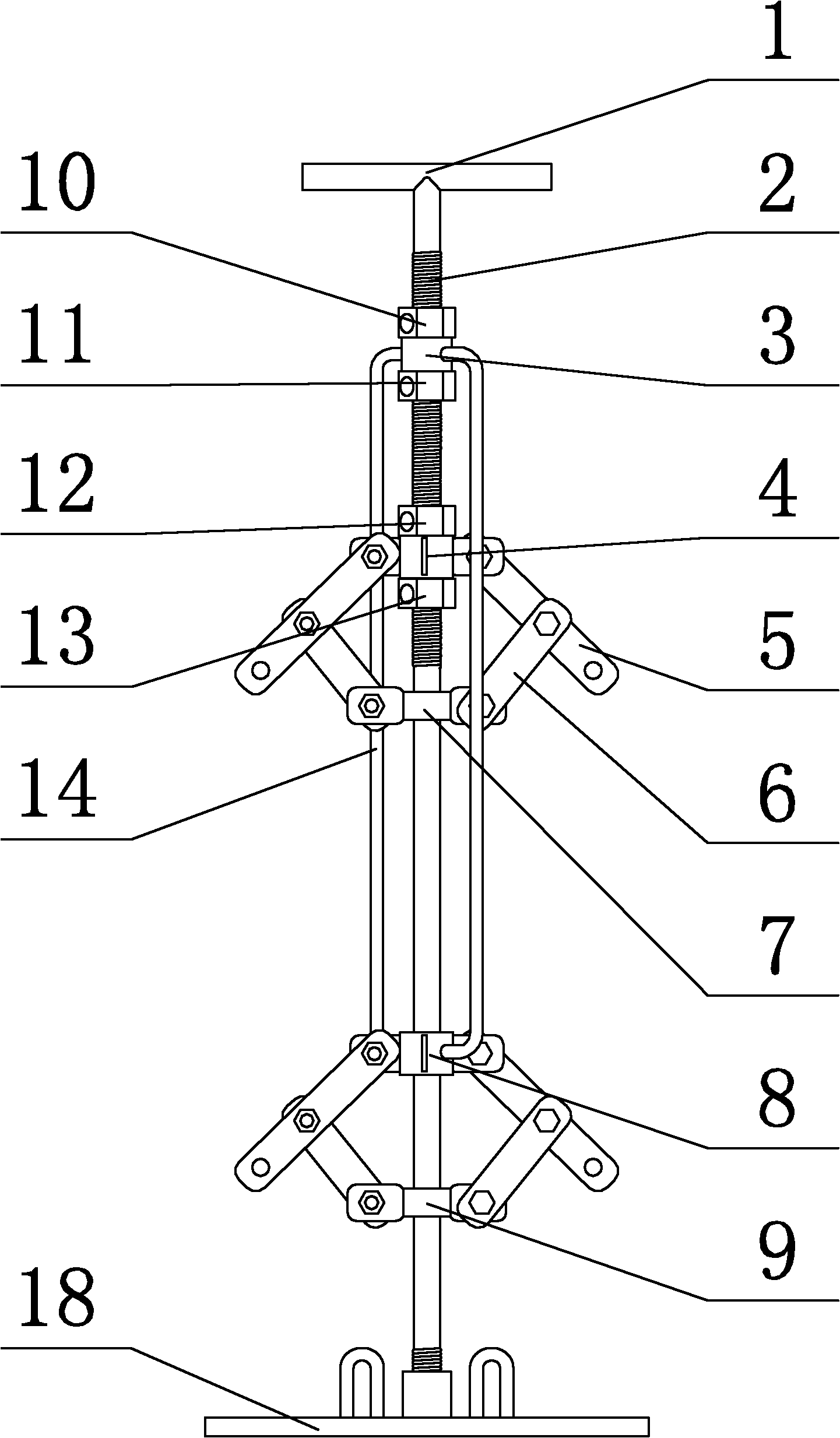
[0026] The first step is to assemble the mold: the equipment foundation reserves a circular anchor bolt hole mold, and its structure is as follows Figure 1 to Figure 3 Shown, it comprises central axis 2, the first stretching and shrinking device, the second stretching and shrinking device, 4 templates 15, 4 seaming plates 17; 4 templates 15 are arc-shaped (the present embodiment 4 templates have the same size), 4 templates 15 are evenly distributed along the circumference, and between the template 15 and the template 15, there are seam repairing plates 17 (the size of the 4 seam repairing plates in this embodiment is the same), and the 4 te...


PUM


Abstract

The invention relates to a construction method for a circular foundation bolt hole reserved for an equipment foundation. The construction method is characterized by comprising the following steps of: step one. assembling a mold for manufacturing the circular hole reserved for the equipment foundation, wherein the mold comprises a central shaft, a first propped open and contracting device, a second propped open and contracting device, four mold plates and four joint sealing plates; the four mold plates are arc-shaped and distributed along the circumference, the joint sealing plates are inserted between the mold plates, and the four mold plates and the four joint sealing plates form a cylindrical space in a surrounding manner; step two. supporting the mold; step three. pouring concrete; step four. removing the mold, and reserving the circular hole; at the moment, plastic films serving as protective layers of the mold plates in the circular hole and cement paste on the surface of the concrete come off in the initial setting and are convenient to clean; and step five. cleaning the hole, and obtaining the circular foundation bolt hole reserved for the equipment foundation. The construction method is simple to operate, is fast in mold dismantling; and the mold can be repeated used.

Description

technical field [0001] The invention relates to a construction method for reserving circular anchor bolt holes for equipment foundations. Background technique [0002] In the construction of the equipment foundation, the foundation bolt holes of the equipment need to be reserved on the concrete foundation. The reserved method generally adopts the methods of supporting steel bellows, plastic pipes or supporting wooden formwork, etc., and removes them in time after the concrete solidifies. The steel corrugated pipe adopts a tool with a slot at one end and a handle at the other end. The slot is clamped to the steel bellows, and the steel corrugated pipe is peeled off layer by layer. The removal effect is not satisfactory; the plastic pipe is baked at high temperature to make it soft, and then Pulling out as a whole, the method sometimes causes the plastic pipe to break off, which directly affects the strength of the secondary grouting of the anchor bolt holes; the wooden formwo...

Claims


Application Information

Patent Timeline
Patent Type & Authority Patents(China)
IPC IPC(8): E02D27/44E04G15/04
Inventor 王平夏春
Owner CHINA FIRST METALLURGICAL GROUP
Why Eureka
Try Eureka