Unsteady sound field separation method

A separation method, non-steady state technology, applied in the field of noise

Inactive Publication Date: 2012-06-13
HEFEI UNIV OF TECH
View PDF2 Cites 17 Cited by
  • Summary
  • Abstract
  • Description
  • Claims
  • Application Information

AI Technical Summary

Problems solved by technology

However, the above-mentioned sound field separation methods only consider the steady-state sound field, and only realize the separation of the sound field in the spatial domain.
When the sound field radiated by the target sound source and the interfering sound source is in an unsteady state, it is necessary to realize the separation of the sound field in the spatial domain and the separation of the sound field in the time domain, so the above sound field separation method will no longer be applicable

Method used


Image

  • Unsteady sound field separation method
  • Unsteady sound field separation method
  • Unsteady sound field separation method

Examples


Embodiment Construction

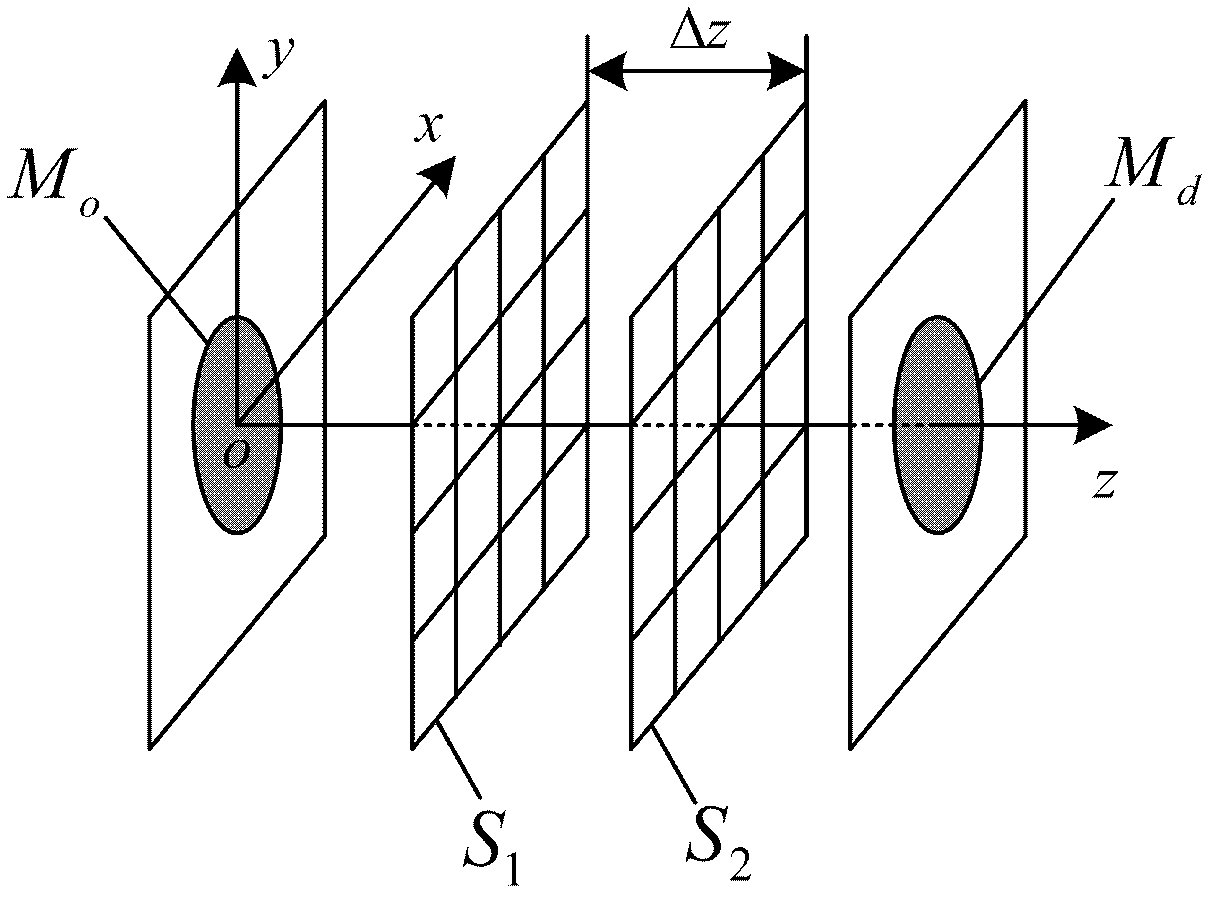
[0113] see figure 1 , in this example, on the measurement surface S 1 The target sound source M is arranged on both sides of o and interfering sound source M d , the disturbing sound source M d Can be a noise source, reflection or scatter source. on the measuring surface S 1 and interfering sound source M d Set between A and the measuring surface S 1 Auxiliary measuring surface S parallel and separated by a distance of Δz 2 . on the measuring surface S 1 with auxiliary measuring surface S 2 There are M measurement grid points uniformly distributed on each. The value of Δz is greater than zero and not greater than the interval of measurement grid points.

[0114] The specific implementation steps are:

[0115] a. A snapshot of the measurement surface S is obtained by using a dual-microphone array 1 with auxiliary measuring surface S 2 The sound pressure time-domain signal on ;

[0116] b. For the measurement surface S 1 and auxiliary measuring surface S 2 The s...


PUM


Abstract

The invention discloses an unsteady sound field separation method, which is characterized by comprising the following steps of: arranging an auxiliary measuring surface S2 which is parallel to a measuring surface S1 and is delta z away from the measuring surface S1 in a tested sound field which has a target sound source Mo and an interference sound source Md simultaneously and radiates unsteady sound pressure signals, and synchronously measuring sound pressure time domain signals on the auxiliary measuring surface S2 and the measuring surface S1; performing two-dimensional space Fourier transform on the sound pressure time domain signals respectively to acquire a sound pressure wave number spectrum; separating a sound pressure wave number spectrum radiated only by the target sound source Mo on the measuring surface S1 through deconvolution operation by utilizing the sound pressure wave number spectrum and a time domain pulse response function; and performing two-dimensional space inverse Fourier transform on the separated sound pressure wave number spectrum, and finally acquiring a sound pressure time domain signal radiated only by the target sound source Mo on the measuring surface S1. By the method, the sound field can be separated in a spatial domain or a time domain; and the method is particularly suitable for separating an unsteady sound field in a non-free sound field environment.

Description

technical field [0001] The invention relates to a sound field separation method in the field of noise in the specialty of physics. Background technique [0002] In actual engineering, the target sound source is located on one side of the measurement surface, and there are often interference sound sources on the other side of the measurement surface. The sound field generated by these interference sound sources affects the accurate measurement of the sound field radiated by the target sound source. Therefore, it is necessary to adopt a certain sound field separation method to separate the influence of the interfering sound source from the measurement results. So far, scholars at home and abroad have proposed a variety of sound field separation methods, which can be roughly divided into five categories: One is the sound field separation technology based on the spatial Fourier transform (SFT): G.V.Frisk et al. first proposed in 1980 to use The SFT method indirectly measures th...

Claims


Application Information

Patent Timeline
IPC IPC(8): G01H9/00G01H17/00
Inventor 毕传兴张小正张永斌徐亮
Owner HEFEI UNIV OF TECH
Why Eureka
Try Eureka