
Performance testing fixture for magnetos
A technology for testing tooling and magneto, which is applied in the field of mechanical tooling, can solve problems such as long manufacturing time, failure to meet development needs, and non-interchangeable models, achieving high versatility, shortening the R&D cycle, and saving R&D costs.
- Summary
- Abstract
- Description
- Claims
- Application Information
AI Technical Summary
Problems solved by technology
Method used
Image

Examples
Embodiment Construction
[0016] Below in conjunction with accompanying drawing and embodiment the present invention will be further described:
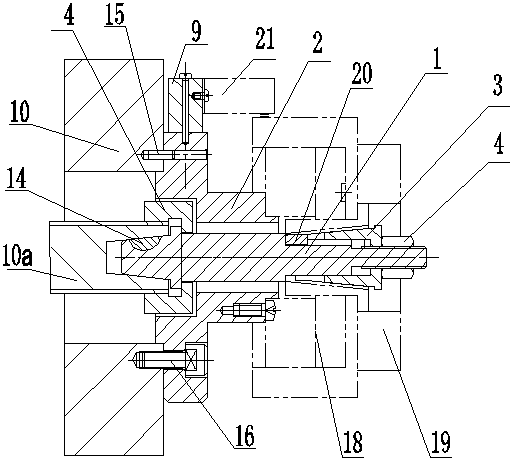
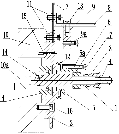
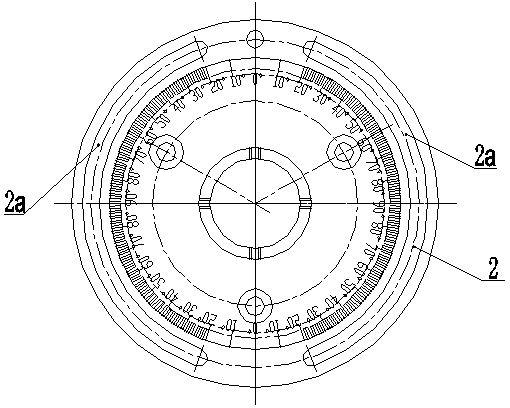
[0017] Such as figure 2 The magnetic motor performance test tool shown is composed of main shaft 1, flange plate 2, taper sleeve 3, lock nut 4, stator positioning block 5, adjusting gasket 6, Y-axis slide rail 7, X-axis slide rail 8, trigger It is composed of device positioning block 9, bolt and nut combination 11 and screw 12, etc. The flange plate 2 is set on the left end of the main shaft 1, the flange plate 2 and the main shaft 1 are fixedly installed on the equipment frame 10 respectively, and the taper sleeve 3 is pressed on the right end of the main shaft 1 by the lock nut 4 . The stator positioning block 5 is fixedly installed on the flange plate 2 and is located on the right side of the flange plate 2. The stator positioning block 5 has a stator fixing hole 5a for installing the stator of the magneto. An adjusting gasket 6 is arranged between the ...
PUM
 Abstract
Description
Claims
Application Information