Lens assembly equipment and method of assembling lens

A technology for assembling equipment and lenses, which is applied in the direction of assembly machines, metal processing equipment, installation, etc., can solve problems that need to be improved, and achieve the effects of improved assembly efficiency, fast moving speed, and high precision

Active Publication Date: 2014-02-19
东莞市研杰自动化设备有限公司
View PDF5 Cites 0 Cited by
  • Summary
  • Abstract
  • Description
  • Claims
  • Application Information

AI Technical Summary

Problems solved by technology

[0015] In summary, the existing lens assembly equipment, regardless of the turntable type or the platform type, needs to be improved in assembly efficiency and assembly yield, so it is urgent to provide a lens assembly equipment and its assembly method with higher assembly efficiency and assembly yield

Method used


Image

  • Lens assembly equipment and method of assembling lens
  • Lens assembly equipment and method of assembling lens
  • Lens assembly equipment and method of assembling lens

Examples


Embodiment 1

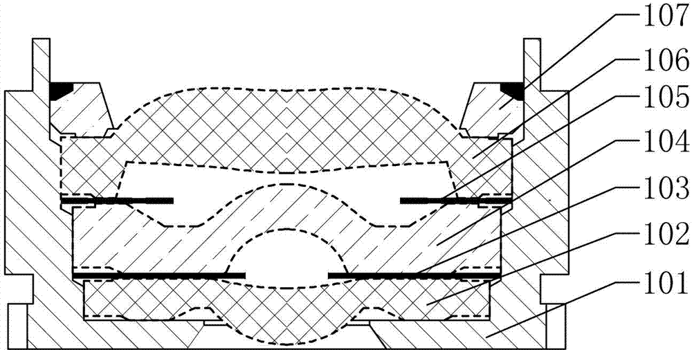
[0072] Such as figure 1 As shown, this embodiment takes assembling a seven-piece camera lens as an example to illustrate the present invention. Of course, the present invention can also be used for three-piece, five-piece, nine-piece or other camera lens assembly. The seven-piece camera lens includes a lens barrel 101, a first lens 102, a lock code one 103, a second lens 104, a lock code two 105, a third lens 106, and a pad that are sequentially stacked in the lens barrel 101 from bottom to top. 片107.

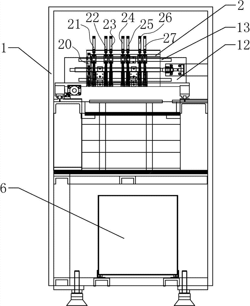
[0073] Such as Figure 2 to Figure 6 As shown, a lens assembly equipment includes a rack 1 provided with an assembly platform. The rack 1 is provided with an assembly unit 2 that can move on a plane parallel to the assembly platform. The assembly unit 2 includes eight The nozzle mechanism that moves in the direction of the assembly platform, one of which is the nozzle mechanism for taking out the lens; the assembly platform is equipped with a jig revolving platform 3, which is equ...

Embodiment 2

[0119] The difference between this embodiment and the first embodiment is as follows: Picture 10 , Picture 11 As shown, the gantry frame 12 is provided with two assembly units 2. The longitudinal movement of the two assembly units 2 is carried by the gantry frame 12 as a carrier. The two assembly units 2 are jointly controlled by a control unit 6 and are synchronized in the gantry frame. 12 moves laterally on the transverse rail 13. Correspondingly, there are two jig revolving platforms 3 and a loading platform 4 on the assembly platform. Of course, on the premise of not affecting the precision control, multiple assembly units 2 can be provided on the gantry frame 12, and correspondingly multiple jig swivel platforms 3 and feeding platforms 4 can be provided on the assembly platform. Therefore, the present invention has Better scalability, which can greatly improve its assembly efficiency.

[0120] The rest of the content of this embodiment is the same as that of the first embo...


PUM


Abstract

The invention relates to the technical field of a lens assembly system, and in particular relates to lens assembly equipment and a method of using the lens assembly equipment to assemble a lens. The lens assembly equipment comprises a frame with an assembly platform and a control unit, wherein an assembly unit capable of moving on the plane parallel to the assembly platform is arranged on the frame, and comprises a plurality of suction nozzle mechanisms capable of moving along a direction vertical to the assembly platform; the assembly platform is provided with a fixture rotary platform which is provided with a plurality of clamp fixtures capable of rotary moving; the assembly platform is provided with a feed platform, and a stock tray is placed on the feed platform; and the control unit controls the assembly unit, the suction nozzle mechanisms and the clamp fixtures to move. By adopting the rotary fixture conveying platform to perform multi-process synchronous assembly, the lens assembly equipment has higher assembly efficiency and higher assembly yield.

Description

Technical field [0001] The present invention relates to the technical field of lens assembly systems, and in particular to a lens assembly device and a method for assembling a lens using the device. Background technique [0002] With the development of technology, portable electronic devices such as mobile phones have been widely used in people's daily life. In recent years, most mobile phones are equipped with digital camera lenses for taking pictures. [0003] When assembling the lens, a clamping fixture is generally used to first fix the lens barrel on the workbench, and then sequentially install the optical elements into the lens barrel one by one. The lens assembly system includes a turntable type and a table top, and a turntable type lens assembly system such as the Chinese Invention Patent No. 200410049690.6 discloses an automated lens assembly system and an assembly method thereof. The method includes: [0004] (A) Make the number jig move intermittently along a conveying di...

Claims


Application Information

Patent Timeline
Patent Type & Authority Patents(China)
IPC IPC(8): G02B7/02B23P21/00
Inventor 肖全忠
Owner 东莞市研杰自动化设备有限公司
Why Eureka
Try Eureka