
Main/standby ETC track system with variable transaction scopes and realization method thereof

An implementation method and technology of lanes, applied in ticketing equipment, instruments, etc., can solve the problems of loss of transaction ability of lanes, inability of OBU to communicate, and low traffic speed, and achieve the effect of ensuring signal coverage, ensuring normal work, and improving traffic speed.

Inactive Publication Date: 2012-06-13
广东利通科技投资有限公司
View PDF4 Cites 6 Cited by
  • Summary
  • Abstract
  • Description
  • Claims
  • Application Information

AI Technical Summary

Problems solved by technology

[0009] 2) A typical ETC lane system has only one antenna. When the antenna is abnormal, the lane loses its ability to trade and can only be closed
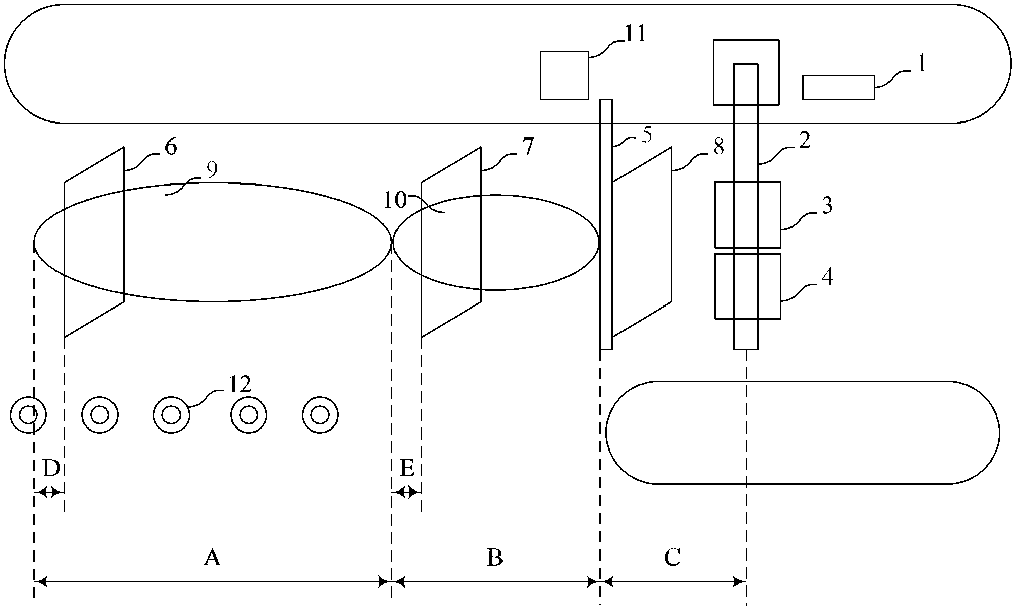
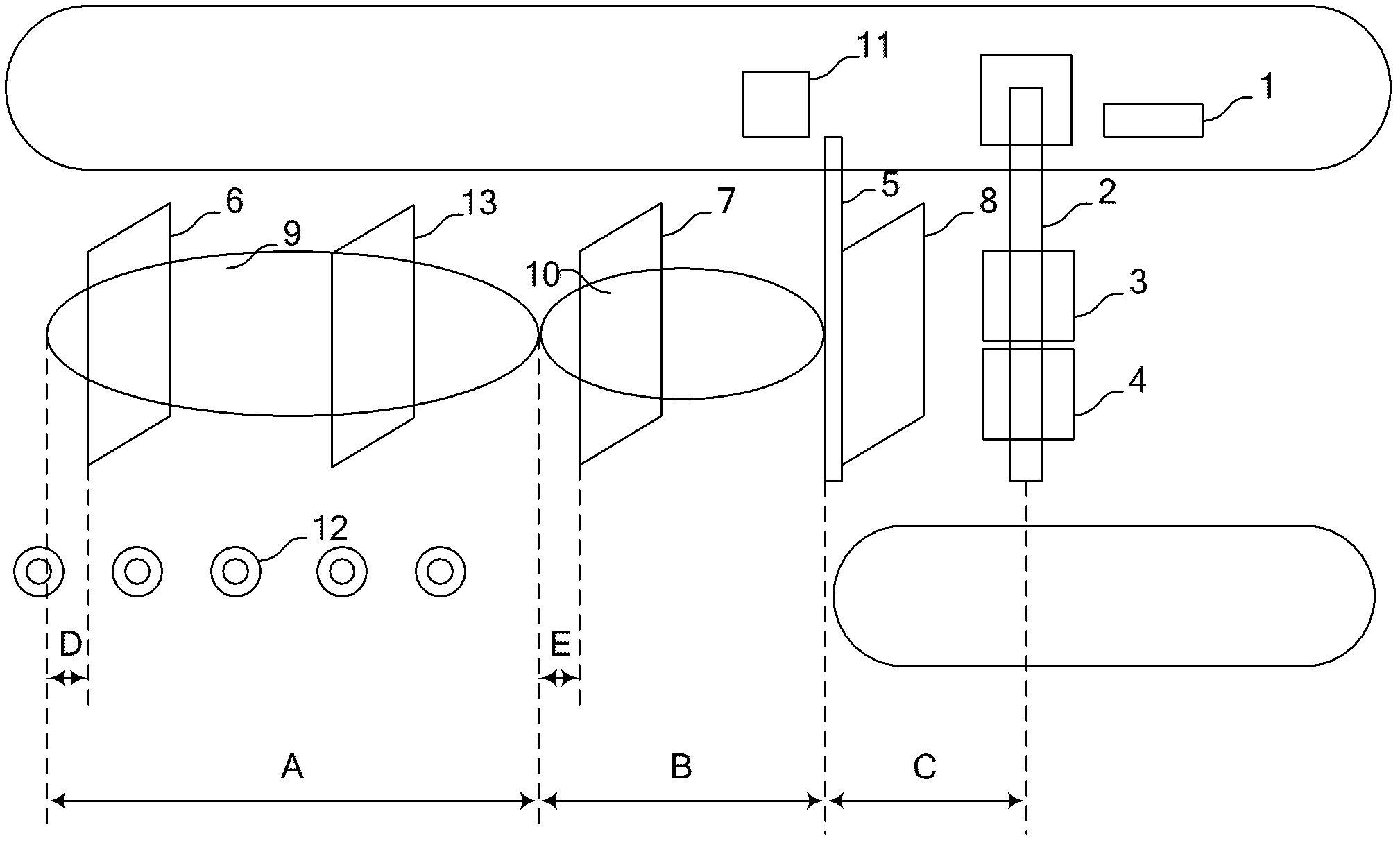
[0010] 3) In a typical ETC lane system, the antenna is located about 2 meters in front of the railing. Due to the directivity of the antenna and OBU, the OBU cannot communicate when it is below the antenna, so there is a communication dead zone of about 2 meters in front of the railing
However, when the antenna in the communication area close to the railing fails, the communication blind area is enlarged compared with the traditional ETC; when the antenna in the communication area far from the railing fails, the communication area is smaller than the traditional ETC and can pass lower speed

Method used


Image

  • Main/standby ETC track system with variable transaction scopes and realization method thereof
  • Main/standby ETC track system with variable transaction scopes and realization method thereof
  • Main/standby ETC track system with variable transaction scopes and realization method thereof

Examples


Embodiment Construction

[0035] In order to make the present invention easier to understand, the present invention will be further described below in conjunction with the drawings, but the embodiments in the drawings do not constitute any limitation to the present invention.

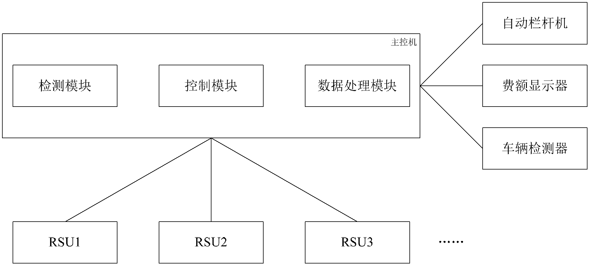
[0036] An embodiment of the present invention provides an active / standby ETC lane system with a variable transaction range, including: a main control computer, an automatic barrier machine, a toll display, two or more roadside read-write devices, and a vehicle detector; Among them, the automatic railing machine, the toll display, the roadside reading and writing equipment, and the vehicle detector are all connected to the main control computer through wireless or wired communication;

[0037] The main control machine includes a detection module, a control module, and a data processing module; the detection module is used to detect whether each roadside read-write device is normal; the data processing module is used to process the...


PUM


Abstract

The invention discloses a main / standby electronic toll collection (ETC) track system with variable transaction scopes and a realization method thereof. The system comprises a main control computer, an automatic barrier machine, an expense display, two or more than two road side read-write devices, and a vehicles detector. According to a direction from which vehicles successively enter, the system divides a main communication area and a standby communication area on an ETC track; when the system does not complete ETC transaction with the vehicles at the main communication area, the standby communication area will be automatically started to carry out the ETC transaction with the vehicles; and when a portion of the road side read-write devices fail to work, the system will adjust power of the road side read-write device that can work normally, so that signal coverage on the vehicles can be ensured and thus a traffic flowing effect can be ensured.

Description

technical field [0001] The invention relates to the technical field of electronic toll collection (ETC), in particular to an active and standby ETC lane system with variable communication range. Background technique [0002] Electronic Toll Collection (ETC for short): refers to the use of on-board equipment installed on the vehicle and roadside equipment installed on the roadside to exchange information during the driving process of the vehicle at the place where toll is required, so that it is fully automatic Complete the entire charging process without stopping. [0003] Roadside Antenna Unit (RSU): It refers to a device that is installed at a toll station, etc., and reads and writes the information stored in the electronic tag (ie: vehicle unit device) through wireless microwave communication. [0004] On-board unit (OBU): refers to the equipment installed on the vehicle, storing vehicle information, and marking the vehicle. [0005] The existing ETC system encounters t...

Claims


Application Information

Patent Timeline
Patent Type & Authority Applications(China)
IPC IPC(8): G07B15/06
Inventor 戴连贵吴穗湘邢万勇周玲李从凡刘正东张宇欢
Owner 广东利通科技投资有限公司
Learn More