
Multi-degree-of-freedom micromanipulator driven by multi-polarization mode piezoelectric actuator

A piezoelectric driver and micro-manipulation technology, applied in piezoelectric effect/electrostrictive or magnetostrictive motors, generators/motors, electrical components, etc., can solve the difficulty of miniaturization of micro-manipulators, rotational motion control Complicated, low motion precision and other problems, to achieve the effect of miniaturization, wide application range and high motion precision

Inactive Publication Date: 2012-06-13
ZHEJIANG UNIV
View PDF3 Cites 18 Cited by
  • Summary
  • Abstract
  • Description
  • Claims
  • Application Information

AI Technical Summary

Problems solved by technology

The other type is a series structure assembled with one-dimensional or two-dimensional motion platforms of similar structure. This type of structure makes each dimensional motion uncoupling as much as possible, which simplifies the problem of model establishment and motion control. However, due to the basic The above is the same type of piezoelectric actuator, and the stacking and assembly of platforms makes it difficult to realize the miniaturization of micromanipulators
And in most micro-manipulator arms, the degree of freedom of rotation is realized by swinging, which makes the control of rotation motion more complicated and the motion accuracy is relatively low.

Method used


Image

  • Multi-degree-of-freedom micromanipulator driven by multi-polarization mode piezoelectric actuator
  • Multi-degree-of-freedom micromanipulator driven by multi-polarization mode piezoelectric actuator
  • Multi-degree-of-freedom micromanipulator driven by multi-polarization mode piezoelectric actuator

Examples


Embodiment Construction

[0028] The present invention will be further described below in conjunction with the accompanying drawings and embodiments.

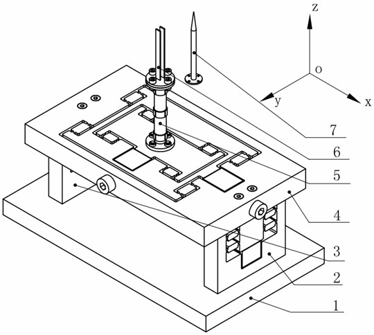
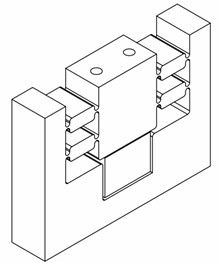
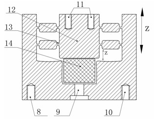
[0029] like figure 1As shown, the present invention includes a base 1, two Z-axis translation micro-motion mechanisms 2 and 3 with the same structure, a nested X-axis and Y-axis translation micro-motion mechanism 4, a Z-axis rotation micro-motion mechanism 5 and an end actuator mechanism, two Z-axis translation micro-motion mechanisms 2 and 3 with the same structure are symmetrically and vertically fixed on both sides of the base 1 through two sets of holes 8 and 10, 15 and 17, and the nested X-axis and Y-axis translation micro-motion mechanisms The two ends of the moving mechanism 4 are connected to the two Z-axis translation micro-moving mechanisms 2 and 3 respectively through two groups of holes 22 and 29, and the Z-axis rotating micro-moving mechanism 5 passes through a group of ring-shaped evenly distributed on the lower flange 33. The hole is con...


PUM


Abstract

The invention discloses a multi-degree-of-freedom micromanipulator which is driven by a multi-polarization mode piezoelectric actuator. The micromanipulator comprises a substrate, a nested x and y axis translation micromotion mechanism, a Z axis translation micromotion mechanism, a Z axis turning micromotion mechanism and an end executive mechanism, wherein three-dimensional translation is realized by using a piezoelectric pile actuator with a piezoelectric strain constant d33 driving a flexure hinge; Z axis turning is realized by using a piezoelectric turning actuator with a piezoelectric strain constant d15 driving a reverse arm; and the end executive mechanism is a micro clamp holder consisting of a piezoelectric double-chip cantilever beam based on a piezoelectric strain constant d31 or a micro injection probe. High accurate micromotions such as the three-dimensional translation, turning around with a Z axis and swing around with an X axis are realized by the drive of the piezoelectric actuator in different polarization modes, and operations such as clamping, transport, probing, injection and the like are realized by different end executive arms. The micromanipulator has the advantages of freedom decoupling, compact structure, flexible operation, convenient control, high motion precision and the like, and the micromanipulator can be applied in the fields of biomedicine, micro electro mechanical engineering and the like.

Description

technical field [0001] The invention relates to a multi-degree-of-freedom micromanipulator, in particular to a multi-degree-of-freedom micromanipulator driven by a multipolar piezoelectric driver. Background technique [0002] With the rapid development of micro-nano technology, manipulation techniques at the "micro / nano" scale are becoming more and more important. As the core component of the micro-operating system, the micromanipulator has been widely concerned by experts and scholars at home and abroad, and has been widely used in cell division, transplantation, cell transgene, probing and injection in the field of biomedicine, micro-electromechanical assembly field Parts processing, positioning, and semiconductor processing and other fields. Therefore, the research on the micromanipulator has important practical application value and broad application prospect. The micro-manipulator directly acts on the micro-operation object to complete the micro-operation task. Ther...

Claims


Application Information

Patent Timeline
Patent Type & Authority Applications(China)
IPC IPC(8): H02N2/02
Inventor 魏燕定娄军强陈德坤杨宇峰
Owner ZHEJIANG UNIV
Learn More