LED drive circuit and switch power supply containing drive circuit

A technology of LED drive and drive circuit, which is applied in the field of LED lighting, and can solve the problems that the input current and input voltage cannot be completely in phase, the PFC is reduced, and the current of the primary winding L1 is discontinuous, etc.

Active Publication Date: 2012-06-13
HANGZHOU SILAN MICROELECTRONICS
View PDF7 Cites 36 Cited by
  • Summary
  • Abstract
  • Description
  • Claims
  • Application Information

AI Technical Summary

Problems solved by technology

from figure 2 It can be seen from the waveforms that the conduction time of the existing isolated flyback single-stage control PFC LED drive circuit is constant, but because the current of the primary winding L1 is discontinuous, the input current and the input voltage cannot be completely balanced. in phase
The PFC of the isolated single-stage PFC LED driver circuit will be reduced

Method used


Image

  • LED drive circuit and switch power supply containing drive circuit
  • LED drive circuit and switch power supply containing drive circuit
  • LED drive circuit and switch power supply containing drive circuit

Examples


Embodiment Construction

[0072] The essence of the invention and specific technical solutions of the present invention will be further described below in conjunction with the accompanying drawings.

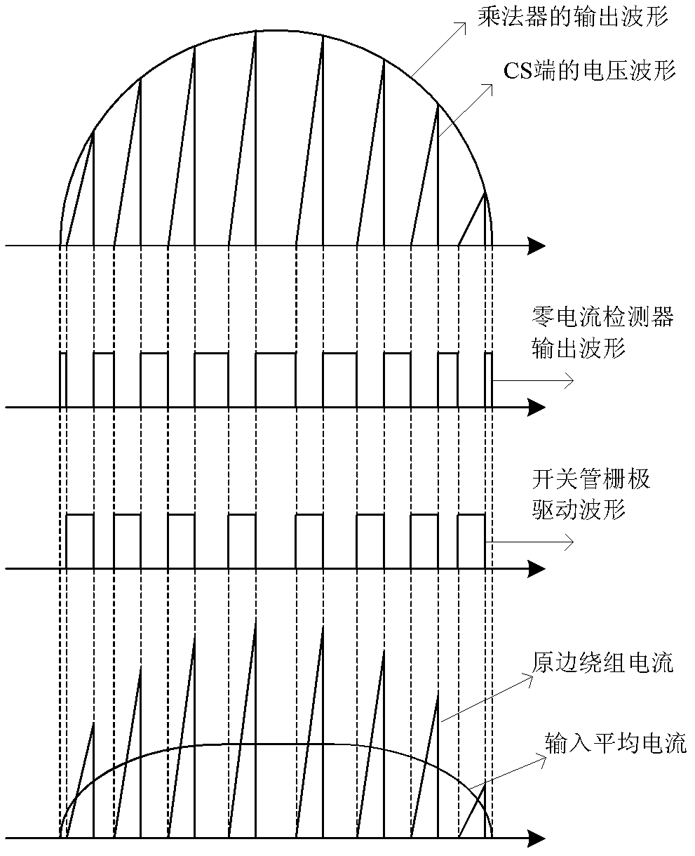
[0073] In order to eliminate the problem in the prior art that the input current and the input voltage cannot be completely in phase due to the current discontinuity of the primary winding L1 , thereby reducing the PFC value of the LED driving circuit. It can be seen from the formula (7) that in the half cycle of the input AC, the conduction time t on is constant if the off-time t off is constant, then the input current can be exactly in phase with the input voltage. However, it can be seen from the formula (6) that the existing LED drive circuit based on the critical conduction mode, the turn-off time t off is and the input voltage V in Proportional, not constant. It will not be described in detail here.

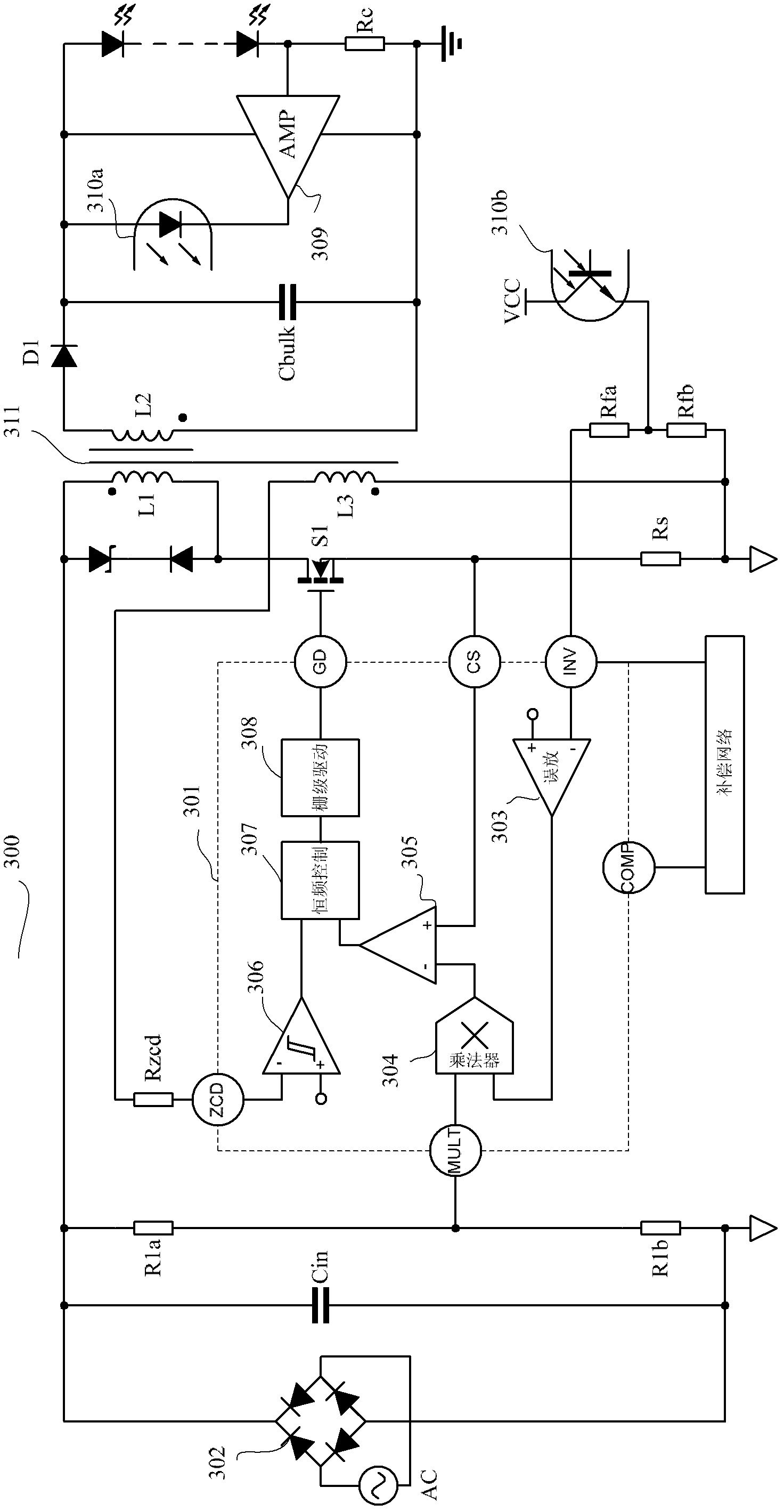
[0074] image 3 It is the topology structure of the switching power supply proposed by the pr...


PUM


Abstract

The invention discloses an LED drive circuit which comprises an error amplifier, a multiplier, a current induction comparator, a zero current detector, a constant frequency control module and a drive circuit. The constant frequency control module is employed in the invention, and turn-off time of a switch tube is fixed and is determined by the constant frequency control module. So when a system is in a half period of input alternating current, switch frequency is not changed any more, the frequency is fixed, and input current and input voltage of a switch power supply are completely same.

Description

technical field [0001] The invention relates to LED lighting technology, in particular to LED driving technology and switching power supply technology including an LED driving circuit. Background technique [0002] As LED technology develops, the brightness and efficiency of LEDs continue to increase. LED lighting for daily households continues to develop, and has gradually become the mainstream of energy saving, emission reduction, and green lighting. [0003] A common AC-powered LED constant current drive circuit with a power factor correction (Power Factor Correction, PFC) function has two structures: an isolated type and a non-isolated type. The isolated structure has two control structures, one is two-level control, and the other is single-level control. Compared with the two-stage control, the single-stage control circuit is relatively simple and the cost is relatively low. The present invention is mainly aimed at the isolated flyback single-stage control PFC LED dri...

Claims


Application Information

Patent Timeline
Patent Type & Authority Applications(China)
IPC IPC(8): H05B37/02H02M7/217H02M3/335
CPCY02B20/42Y02B20/40
Inventor 汤仙明姚云龙
Owner HANGZHOU SILAN MICROELECTRONICS
Why Eureka
Try Eureka