Core drill and coring method

A technology for core drilling and core drilling bits, which is applied in earth-moving drilling, extraction of undisturbed core devices, wellbore/well components, etc., can solve problems such as inability to observe cores, and achieve the effect of avoiding complexity

Inactive Publication Date: 2012-06-13
HALLIBURTON ENERGY SERVICES INC
View PDF7 Cites 7 Cited by
  • Summary
  • Abstract
  • Description
  • Claims
  • Application Information

AI Technical Summary

Problems solved by technology

[0007] All of these devices have the drawback that at the surface, the core cannot be viewed without manipulating the inner tube until the inner tube is opened

Method used


Image

  • Core drill and coring method
  • Core drill and coring method
  • Core drill and coring method

Examples


Embodiment Construction

[0033] In the various figures, the same or similar elements have the same reference numerals.

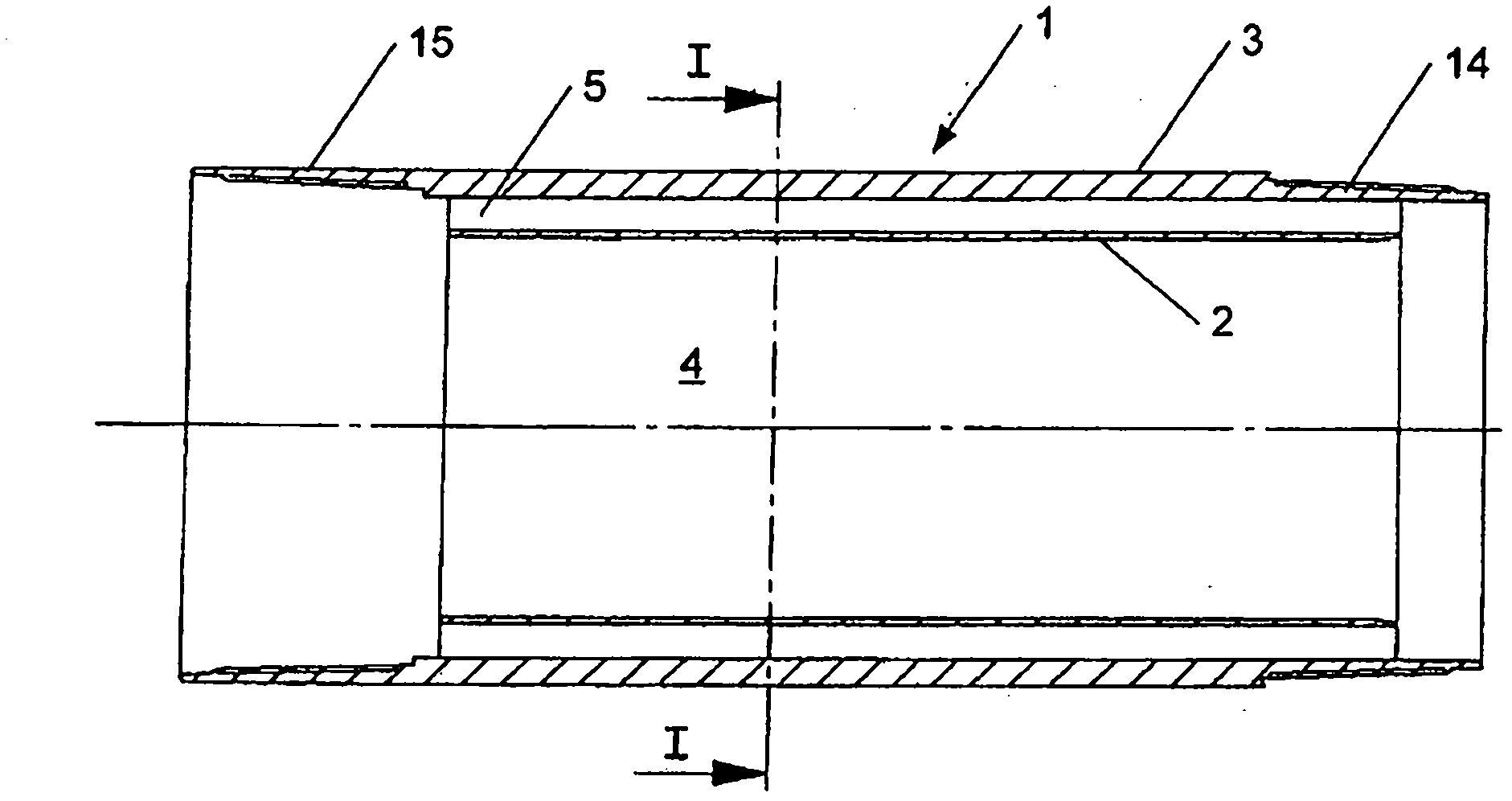
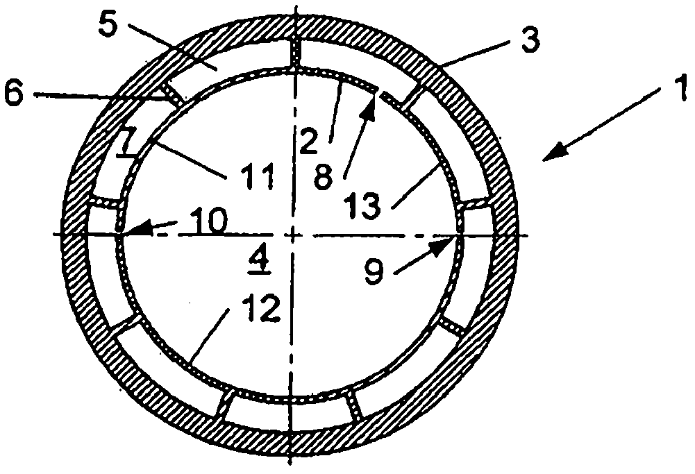
[0034] Such as figure 1 and 2 clearly shown in ( figure 1 and 2 An example of an inner coring tube 1 that can be used in the inventive coring drill or coring method is shown), the inner coring tube 1 being designed in the form of a double-walled tube. It comprises an inner tubular wall 2 and an outer tubular wall 3 . The inner tubular wall 2 will receive the core in its cavity 4 . It is housed coaxially inside the outer tubular wall 3 while being held radially at a distance therefrom so as to form an annular space 5 between the inner and outer tubular walls. Especially as figure 2 As shown in , the tubular walls 2 and 3 are firmly connected to each other so as to form a one-piece assembly.

[0035] The shown inner core tube is preferably capable of being manufactured from metal or plastic material, or from a material based on metal or plastic material. Preferably it can be ...


PUM


Abstract

Disclosed is a core drill comprising: an external pipe; a coring bit to be rotated by rotation of the external pipe to drill a coring hole and form a core having a core diameter; and an internal coring pipe (1), mounted within the external pipe, to receive a core formed by the coring bit, the internal coring pipe comprising: an internal tubular wall (2) defining a cavity (4) having a diameter substantially the same as the core diameter within which to retain a core formed by the coring bit, one or more viewing openings (8, 9, 10) being formed through the internal tubular wall; and an external tubular wall (3), in which the internal tubular wall is housed coaxially, the internal and external tubular walls being connected to each other so as to form a single-piece double-walled pipe.

Description

technical field [0001] The present invention relates to core drills and related coring methods. Background technique [0002] For example, a core drill to be used in oil exploration comprises in a known manner: an annular core bit; an outer tube which supports and rotates the annular core bit; and an inner core tube which will receive the core. The inner core tube is housed coaxially inside the outer tube, for example by means of roller bearings which enable the outer tube to drive the inner tube axially and in rotation around the inner tube without driving it in rotation. In a known manner, a plurality of outer pipes and a plurality of inner pipes can be assembled in succession in a string. The front inner tube (considering the direction of travel of the drill when cutting the core) carries in the usual way a generally split frusto-conical ring system which will The core is held in the cavity of the inner tubing string. [0003] Core drills of the type described above h...

Claims


Application Information

Patent Timeline
Patent Type & Authority Applications(China)
IPC IPC(8): E21B25/06E21B49/02
CPCE21B25/02E21B25/06E21B49/02
Inventor O・J-M・C・马热朗
Owner HALLIBURTON ENERGY SERVICES INC
Why Eureka
Try Eureka