Fully-automatic corner packaging method and device on ceramic tile packaging line
A packaging line and fully automatic technology, which is applied in the field of ceramic tile packaging, can solve problems such as uneven corner edges and no solutions have been considered, and achieve the effects of reducing equipment manufacturing costs, saving energy, and simplifying equipment construction.
- Summary
- Abstract
- Description
- Claims
- Application Information
AI Technical Summary
Problems solved by technology
Method used
Image
Examples
Embodiment 1
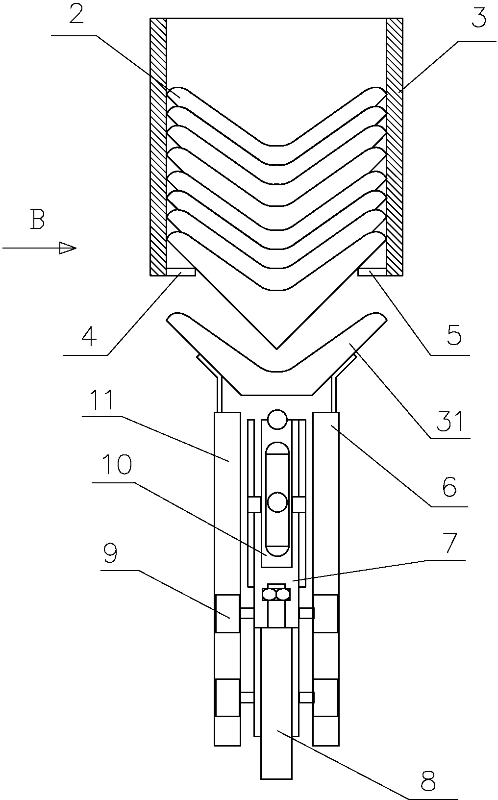
[0045] Figure 4 , 5 , Shown in 6 is the first wrap angle device. A corner protector 3 is vertically arranged on the frame, and support bars 4 and 5 are respectively arranged on both sides of the lower end of the corner protector 3 . Guide rails 6 and 11 are arranged below the corner guard bin 3, and the two guide rails are connected together by connecting plates. A slide plate 7 is arranged between the guide rails 6 and 11, rollers 9 are arranged on both sides of the bottom of the slide plate 7, and a cylinder 8 is connected at the bottom of the slide plate. Each hinge swing clamp arm 10 is hinged on both sides of the upper part of the slide plate 7, and the upper end of the swing clamp arm 10 is fixed with a needle 16. On the upper end of slide plate 7, angle guard 31 is fixed, and the bottom end of angle guard 31 is open. A magnet 15 is arranged on the slide plate 7 , and the magnet 15 is located between the slide plate 7 and the swing clamp arm 10 . A swash plate 12 i...
Embodiment 2
[0054] Such as Figure 8 As shown, compared with Embodiment 1, this embodiment makes the following changes to the structure of the control swing clamp arm: each of the guide rails 6, 11 is fixed with a push pendant 18, and the push pendulum is actually a slant plate, and the two push pendant 18 The bottom slopes inward. The two swing clamp arms 10 are intersected together, and a rotating shaft 17 connected with the slide plate 7 is arranged at the intersection. A spring 19 is arranged between the lower half of the two swing clamp arms 10 .
[0055] The working process of the present embodiment is set forth below:
[0056] Cylinder 8 works and pushes slide plate 7 to move upwards along the inner walls of guide rails 6 and 11. Slide plate 7 drives swing clamp arm 10 and corner protector 31 to move upward together. Sheet angle guard 2 is received in the angle guard bucket 31. The corner protector 31 continues to move upwards to hold up the entire corner protector string. At t...
Embodiment 3
[0058] Such as Figure 9As shown, compared with Embodiment 1, this embodiment makes the following changes to the structure of the control swing clamp arm: a cam 28 is set between the two swing clamp arms 10, and the contour surface of the cam 28 can be in contact with the swing clamp arm 10 , fix the toggle lever 27 on the rotating shaft 30 of the cam 18 . A fixed mount 26 is set on the frame.
[0059] The working process of the present embodiment is set forth below:
[0060] Cylinder 8 works, and pushes slide plate 7 to move upwards along the inner wall of guide rail 6,11, and slide plate 7 drives swing clamp arm 10, angle protector 31 to move upward together, and angle protector 31 wraps up the bottom double protective sheet angle protector 2, double The protective sheet angle guard 2 is received in the angle guard bucket 31. The corner protector 31 continues to move upwards to hold up the entire corner protector string. At this time, the corner protector string is affect...
PUM
 Abstract
Description
Claims
Application Information
 - R&D
- Intellectual Property
- Life Sciences
- Materials
- Tech Scout
- Unparalleled Data Quality
- Higher Quality Content
- 60% Fewer Hallucinations
Browse by: Latest US Patents, China's latest patents, Technical Efficacy Thesaurus, Application Domain, Technology Topic, Popular Technical Reports.
© 2025 PatSnap. All rights reserved.Legal|Privacy policy|Modern Slavery Act Transparency Statement|Sitemap|About US| Contact US: help@patsnap.com


